Simple NOAA/Meteor Weather Satellite Antenna: A 137 MHz V-Dipole
Over on his blog Adam 9A4QV (seller of various RTL-SDR related goods including the LNA4ALL) has just made a post detailing a build of a high performance super simple NOAA/Meteor M2 weather satellite antenna. Most antenna designs for polar orbiting weather spacecraft are based on circularly polarized turnstile or QFH designs. However, Adams antenna is based on a very simple linearly polarized dipole, which makes construction almost trivial.
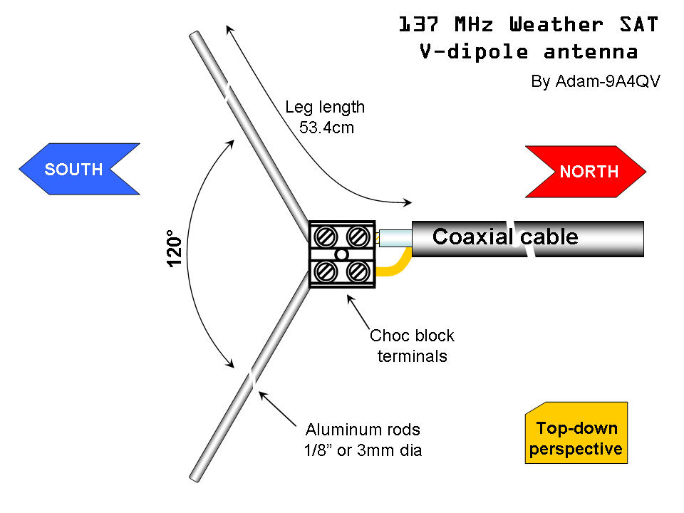
The idea is that by arranging a dipole into a horizontal ‘V’ shape, the radiation pattern will be directed skywards in a figure 0 (zero) pattern. This will be optimal for satellites travelling in front, above and behind the antenna. Since polar orbiting satellites always travel North to South or vice versa, we can take advantage of this fact simply by orienting the antenna North/South.
There is also another advantage to Adams design. Since the antenna is horizontally polarized, all vertically polarized terrestrial signals will be reduced by 20 dB. Most terrestrial signals are broadcast in vertical polarization, so this can help significantly reduce interference and overloading on your RTL-SDR. Overloading is a big problem for many trying to receive weather satellites as they transmit at 137 MHz, which is close to the very powerful FM broadcast band, air band, pagers and business radio. In contrast a circularly polarized antenna like a QFH or turnstile only reduces vertically polarized terrestrial signals by 3 dB.
As the satellites broadcast in circular polarization there will be a 3 dB loss in Adams design from using a linear polarized antenna. But this can be considered as almost negligible. Adam also argues that the home construction of a QFH can never be perfect, so there will always be at least a ~1dB loss from inaccurate construction of these antennas anyway.
The final advantage to Adams design is that construction is extremely simple. Just connect one element to the center coax conductor, and the other to the shield, and spread apart by 120 degrees.
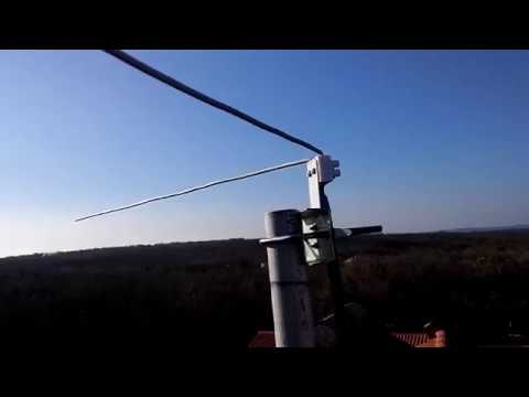
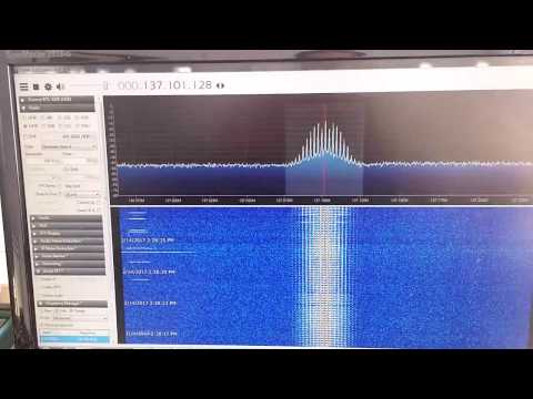
Adam has tested the antenna and has gotten excellent results. If you want more information about the antenna design, Adam has also uploaded a pdf with a more indepth description of the design and his thoughts.


This is so awesome. I remember when gearing up for SSTV images from the ISS everyone was talking circular polarized cross yagis and “bare minimum an egg beater” and so forth. I used a vertical dipole physically tuned to resonate on the downlink frequency and got the images perfectly, even ones that should have been entirely out of my footprint from reflections and scatter. I’m sure in this case the horizontal V is far better, I’m just saying… you never know until you try. You can’t just listen to theory passes and passed.
Are there any comparisons of QFH vs bent dipole vs twin phased dipoles? I built a bent and it did quite well above 15 degrees with weak spots and the QFH only seemed to do well above 35 degrees elevation.
I’ve covered one in hot melt glue, been up a couple of years now.
The terminal block is a real villain here, though it may useful for some field test, not for permanent setup at outdoor. Dipole element weight cause change of angle and damage of block.
The “penn-union asrb-11-2-2 aluminum splice reducer block” is readily available and inexpensive.
Sometime soon I’m going to test my antenna with a VNA and see what the real resonant frequency is, I don’t expect it to be far off, but I’m not so certain that it will be 50ohm impedance.
It was spot on 137MHz!
Glad to see this discussion is not dead!