Tagged: mods

Mods and Performance of an R820T2 RTL-SDR

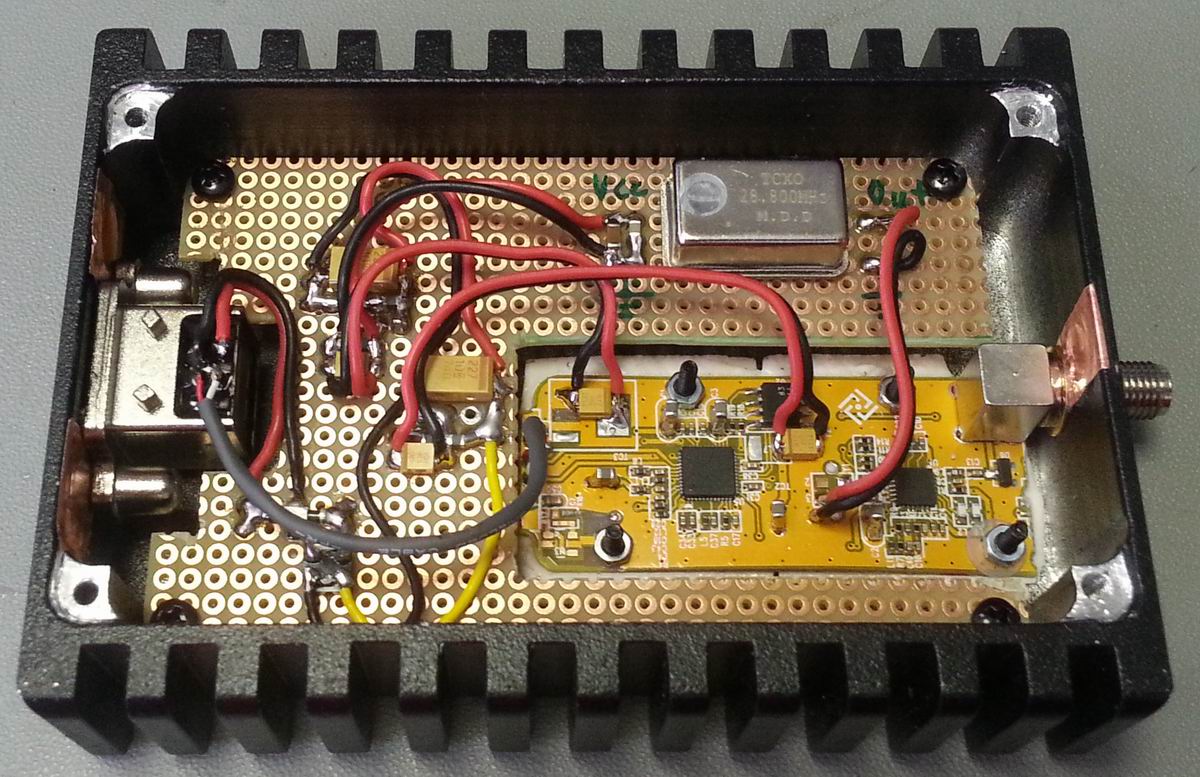
Over on his blog, RTL-SDR experimenter Laidukas had added a post showing how he modded his R820T2 RTL-SDR for improved noise performance. The mods he applies are:

  • Addition of 100nF, 1nF and 100pF bypass capacitors on the power supply rail.
  • Added a common mode choke to the 5V line.
  • Added a MuRata NFM21 EMI suppression filter to the 5V line.
  • Replaced the oscillator with a 0.3 ppm temperature controlled oscillator (TCXO).
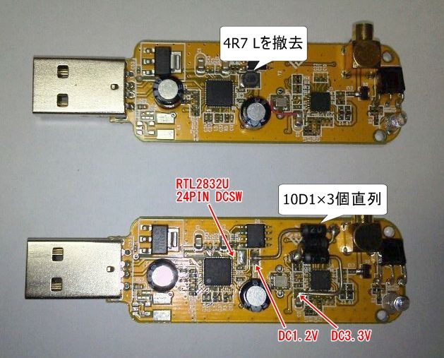
  • Disabled the internal RTL2832U 1.2V switching supply and provided external 3.3V and 1.2V supplies.
  • Replaced the MCX connector with an SMA female connector.
  • Enclosed circuit in a metal box.
Modded R820T2 RTL-SDR Dongle

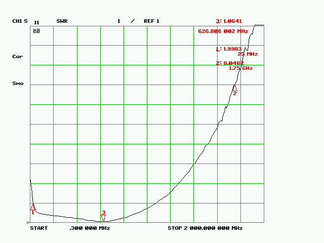
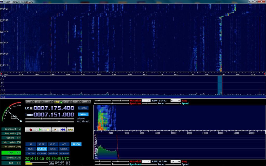
In addition to the mods, Laidukas also made some measurements on the performance of the R820T2 on some metrics. In the first test he measured the input insertion loss or SWR. He found that the SWR was below 2 between frequencies of 25 MHz to 1076 MHz. At higher frequencies the SWR reached levels up to about 8.

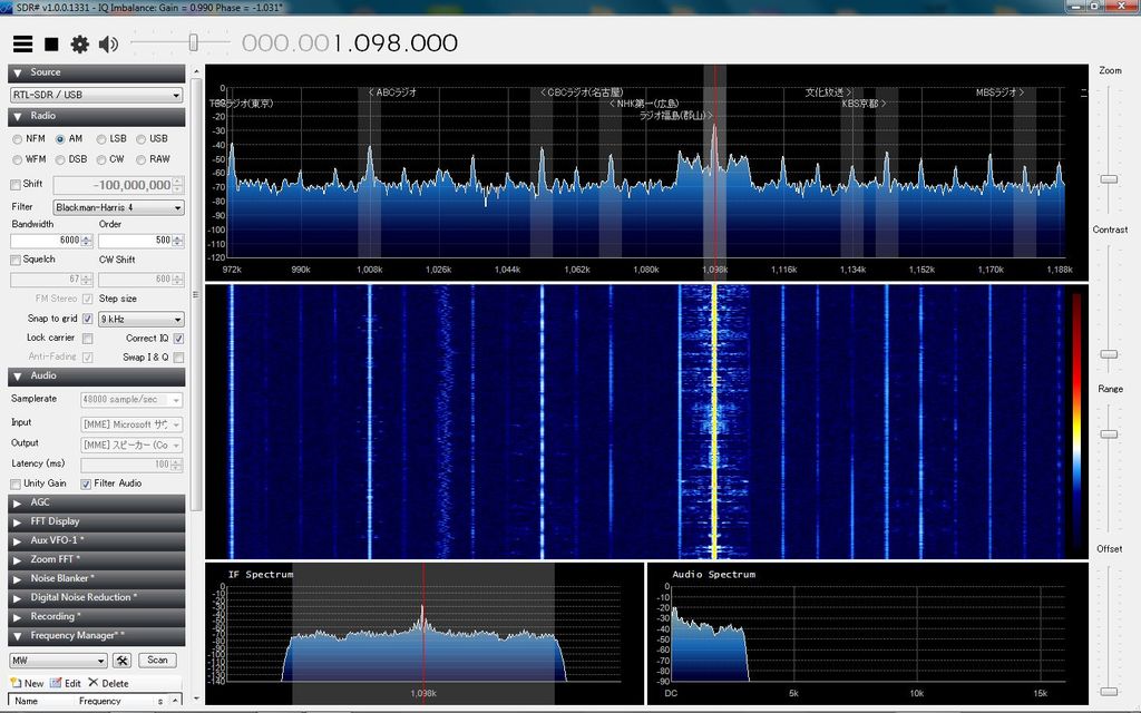
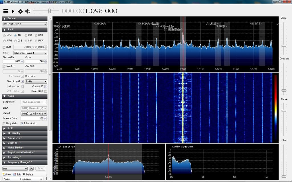
Another test showed that with the LNA disabled the R820T2 had a lower noise floor by about 7dB, when compared to the R820T.

SWR Plot of the RTL-SDR Antenna Input
SWR Plot of the RTL-SDR Antenna Input with LNA disabled

Updates to Removing the 1.2V Switching Power Supply on the RTL-SDR

A few months ago we posted about how a Japanese RTL-SDR modder disconnected the noisy 1.2v switching power supply on the RTL-SDR and replaced it with three diodes. The diodes reduced the voltage from the 3.3v line to 1.2v. It seems that most of the improvements seen from the previous post were inconclusive, as soon after he realized that there are minor dongle to dongle variations in sensitivity, so he could not be certain if the improvement was due to his modifications.

However, he has continued to modify the RTL-SDR using the same principal (Japanese, use Google Translate). He discovered that to fully suppress the 1.2v switching regulator pin 27 on the RTL2832U chip must be connected to ground. Once this is done the switching noise present at 1 MHz disappears, although there does not seem to be any significant improvement in noise anywhere else.

The first screenshot shows an unmodded dongle with the switching regulator still connected. There is some noise present at around 1.026 MHz. The second image shows a modded dongle, the noise at 1.026 MHz is gone.

Switching regulator on. Noise can be seen at around 1.026 MHz.
Switching regulator off. Noise at 1.026 MHz is gone.
The 3 diode mod.
The three diode mod.

Improving HF Reception By Disconnecting the Switching Power Supply on the RTL-SDR

By using an upconverter, direct sampling mod, or experimental software driver the RTL-SDR can be used for HF reception. However, a problem with HF reception and the RTL2832U chip is that it uses a switching power supply in its design. This switching power supply causes significant amounts of noise spurs to appear in the HF spectrum.

Japanese RTL-SDR experimented ttrftech has recently posted about a modification to the RTL-SDR which he performed (note in Japanese, use Google translate to read). The purpose of the switching power supply in the RTL2832U is to step 3.3v down to 1.2v. In his modification, ttrftech disconnected the switching power supply and instead stepped 3.3v down to 1.2v by using three diodes. This works as each diode has a voltage drop across it of 0.7v.

His results show that there is a significant reduction in noise spurs at HF frequencies.

Switching power supply replaced by three diodes.
Unmodded reception at 7 MHz
Modded reception at 7 MHz