A Homemade Magnetic Loop Antenna used with RTL-SDR Direct Sampling
Over on our forums user "SandB" has submitted his designs for a homemade magnetic loop antenna with preamp that he uses together with his RTL-SDR in direct sampling mode. The antenna looks like an interesting build so we are resharing it here. He writes:
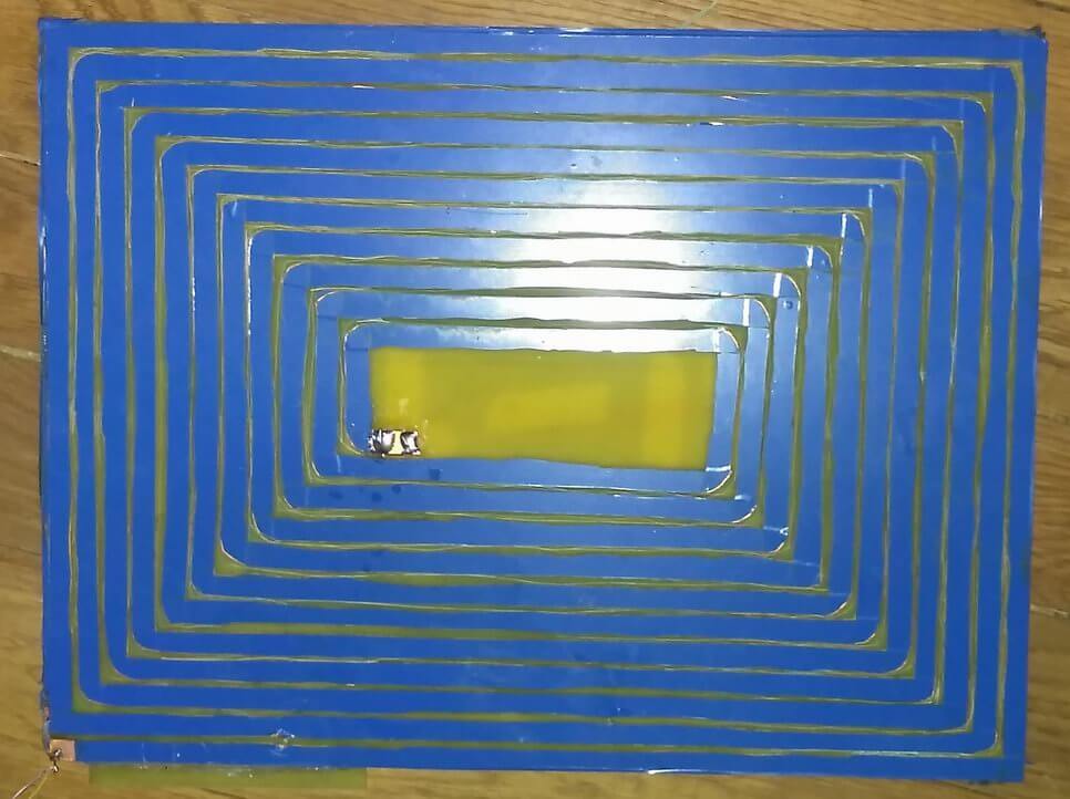
So, antenna itself represents as handmade on-PCB winding made of two-side-foiled fiberglass size of 30x40 cm. Both 'windings' connected in the middle and thus winded to 'continue' each other.
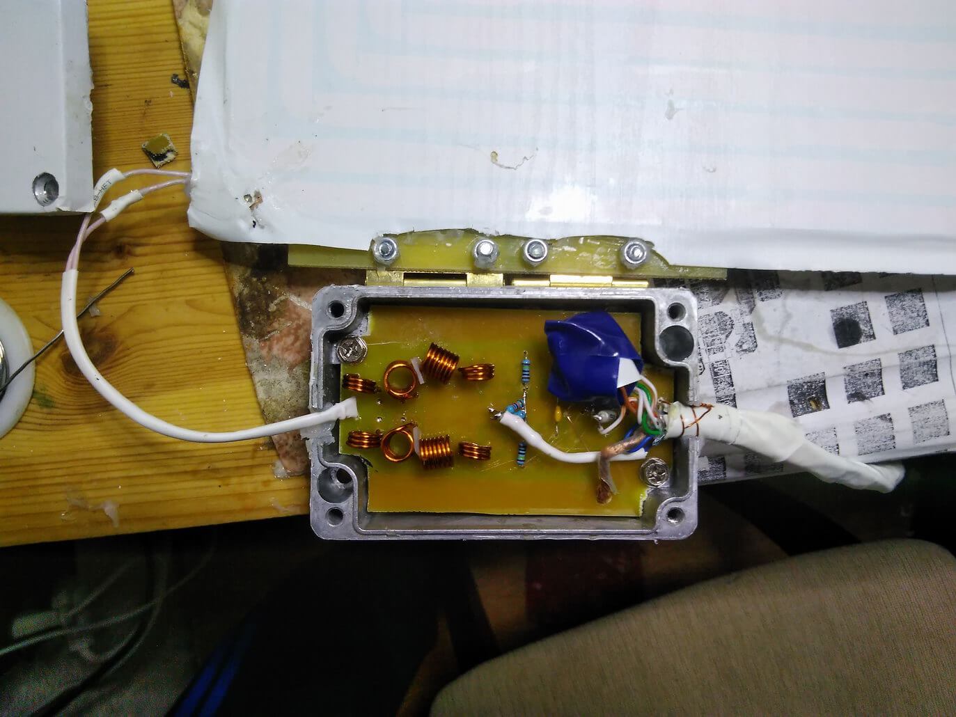
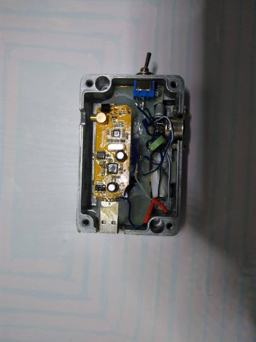
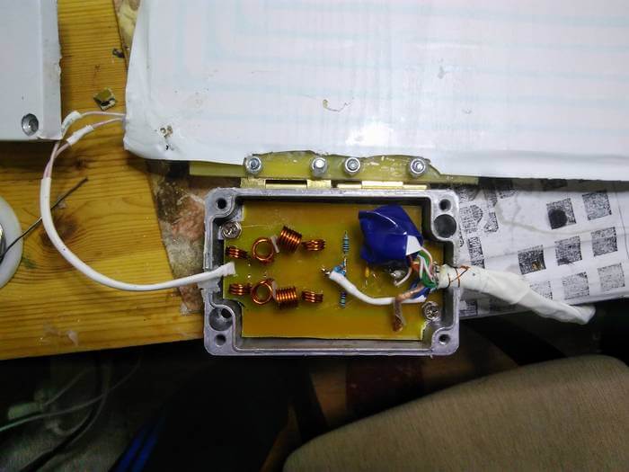
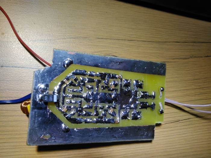
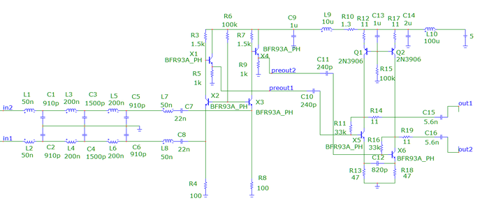
Preamp located in metal box attached to antenna and connected via 1.5m S/FTP cable to another box with RTL stick. Note that some transistors soldered on PCB in upside-down - dot on layout means base.
Electrically preamp made as 3-stages balanced signal amplifier with low-input impedance and low-pass filter before input with cut-off at 15MHz. Such complications were required to reduce interferences and intermodulations. Antenna itself is more effective on long-medium waves, so preamp has higher gain on short waves (gain varies from 45db at 200KHz to 68 db at 10MHz - see attached freq responce pic). Getting more flat responce at lower frequencies is possible by increasing C10/C11/C12 to 22nF.
My implementation has some additional elements to make possible to adjust preamp's gain in few db's. But seems its quite useless so that details not included in this post. Anyway, its possible to reduce gain by increasing R6 to 500K.
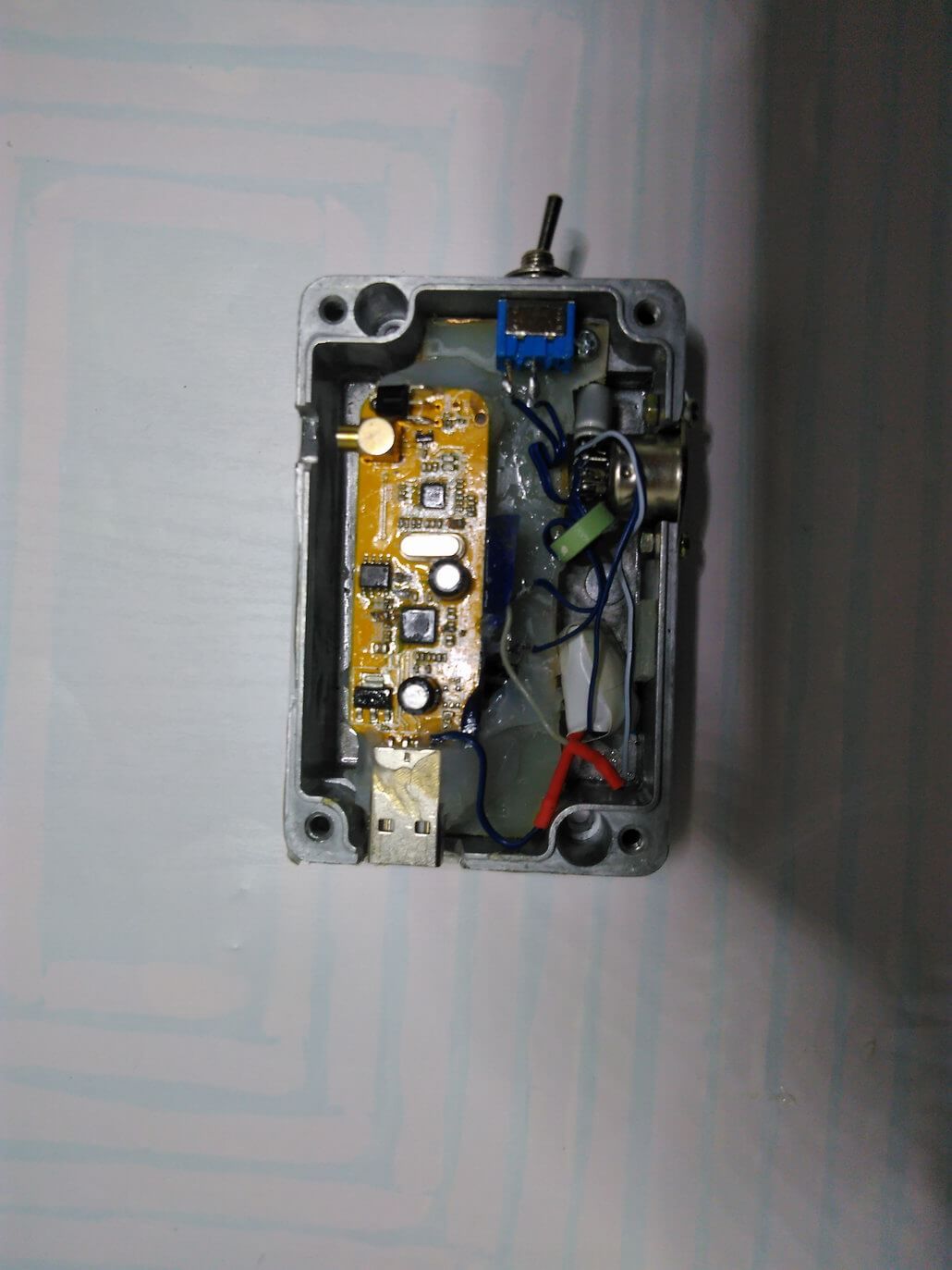
Box with RTL SDR: I put both signal wires as 3 windings via ferrite ring with high permeability just before RTL chip. This noticeable reduced stray interference, that induced in that cable but doesn't affect differential signal.

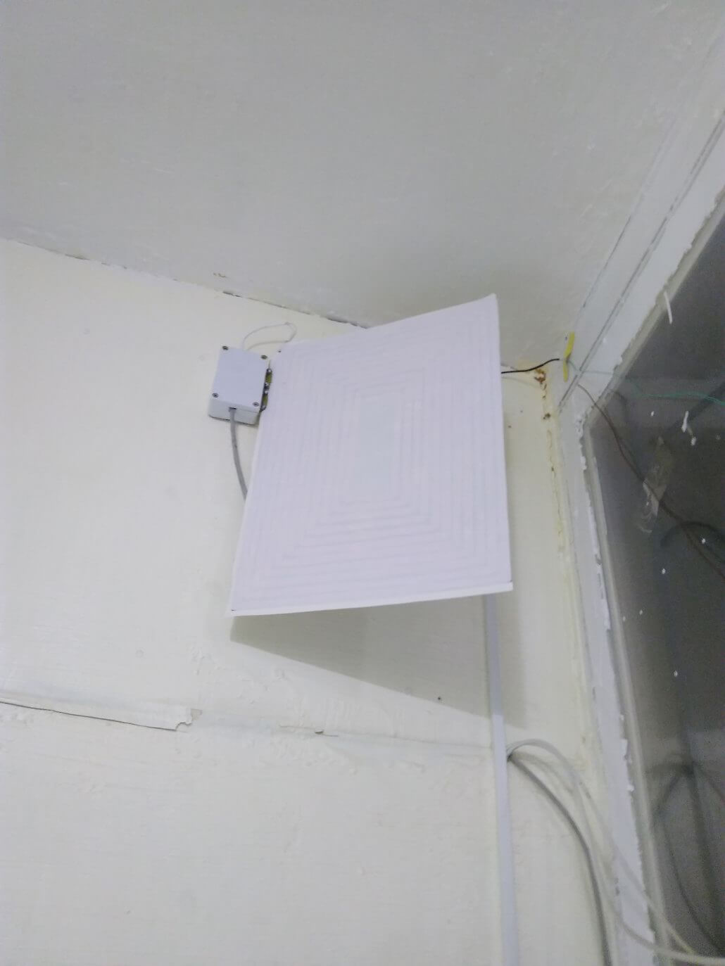


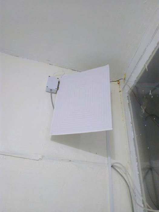


If this is considered an active antenna, you should not mount it inside the house. This is against all radio laws. Inside the home there is one major source of disturbances that pushes out the weak outside signals.
Moving away from local interference source always good, but not always possible idea. Small magnetic loop antennas known to be less sensitive for such kind of interference that ‘usual’ antennas.
Hi SandB, when i said uncertain results i did not mean the uncertainty of the project but the uncertainty of the assembly work and coils winding 🙂
I know that a very low input impedance is required, i just picked randomly up one of the differential amplifiers that i have seen to explain the concept, maybe on others the impedance can be adjusted adding and replacing a few components. That was more an invite to investigate if there is something cheap that can be adjusted easily than a suggestion for a possible solution 😀
That amplifier you mentioned has extremely high input impedance, while wideband magnetic loop has extremely low output impedance. However it can be used instead of everything in my circuit _after_ 1st differential stage (that effectively converts impedance). Using high-input impedance as loop amplifier directly besides of obvious inefficiency due to impedance mismatch also will cause much of electric interference to affect amplifier’s input.
As for results: before this mod I didnt hear almost anything on LW/MW partially due to excessive interferences, now I can hear several stations on LW, see full MW band and, depending on date time – full some SW bands.
Also can receive (with much noise, but hearable) 160m hams with ~500W transmitter at distance of ~800km. Not bad for completely indoor antenna and I even didnt try to rotate it to find right direction.
As for caveats. I was worried that amplifier of such big gain will be self-oscillating. And actually I still afraid that it is but I just dont see this. I planned to perform some extreme tests to reveal such problem if its hidden and will update forum if will find any.
Anyway, obvious way if one will see self-oscillation – reduce gain (by increasing R6 by 2..3 times). Currently gain is enough to work without activating RTL’s amplifier.
About price: amplifier itself cost near to nothing: 10 transistors cost 1.30USD on ebay. Most of price was consumed by aluminium boxes and big fiberglass plate. Selection of fiberglass was also not sudden decision. As I said, magnetic loop antenna has very low impedance, that means its efficiency notable affected by active resistance of wires, and, on high frequencies, resistance of wires notable affected by skin-effect. So, to make more efficient antenna with many windings its better to make them from flat but not round wires. Many windings was chosen by its turn to achieve better impedance matching with amplifier. Single winding would have < 1 Ohm impedance, its impossible to make amp with such low impedance, and using transformer will introduce its own signal losses.
Good! but a lot of work with uncertain results for most of us. I am more for the simple mods. I wait that somebody with lab equipment test and adapt some commercial amplifier like this for a wideband active loop.
Congratulations to SandB anyway.
p.s. actually Carl should come up with a ready made circuit for this, not everybody want to spend $100 for the excellent LZ1AQ circuit or $400 for a Wellbrook 🙂