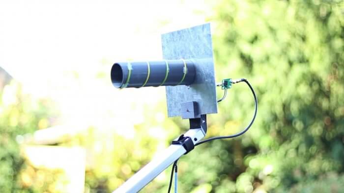
Building a 3D Printed LHCP Helical L-Band Feed for Inmarsat, AERO and HRPT
Thanks to Manuel a.k.a. Tysonpower for submitting his latest YouTube video tutorial about building an 1550 MHz L-band LHCP helical antenna for receiving satellite signals such as Inmarsat, AERO and HRPT.
Manuel's design is based on a 3D printed part which is used to accurately form the helical winding. The winding then mounts onto an aluminum plate and a satellite dish arm using a custom 3D printed adapter for the dish arm. In the video he uses the helical feed with an 80cm satellite dish and a standard 40mm LNB mount on the dish arm. Attached to the feed are two LNAs in series which help to lower the noise figure and reduce losses in the coax cable.
With this setup he writes that he was able to get very good AERO and Outernet reception from Alphasat (25E geostationary). He also writes that he's had good results using it for HRPT reception as well.
The 3D printing STL files and list of parts required are available on Thingiverse, and the companion video is shown below. Note that the video is narrated in German, but English subtitles are available.

Would you be willing to sell me a completed feed?
Jeff
K2SDR
Sorry Jeff, but I will not sell these Feeds.
Also the Shipping to the US would be quite expensive 🙂
If you don’t have a 3D Printer, just ask a friend or serach on the Internet on a 3dhub for someone that will print it out for you. The rest of the assembly is done in just a couple of minutes.
Oh nice project 🙂 I did something similar- check this: https://www.thingiverse.com/thing:2310701
Did You think about impedance matching problem?
Same question as for the other designer – what software did you use for the 3D design? and how did you make the spiral groove cutout? Also, did you find any documentation on how/why the triangle stub works, and how to design/dimension it for different frequencies? All I’ve been able to find is templates for specific frequencies and nothing about why.
Software: SolidWorks
Spiral groove cutout: It’s 3d printed, so i just designed It (i don’t know if I understand the question)
Impedance matching triangle: it’s big topic on RC forum about matching problem: https://www.rcgroups.com/forums/showthread.php?1377791-Circularly-Polarized-Helical-antenna-7-5-13-dbi-New-Wave-Trap-match!
Design/dimension: I used this calculator: http://www.daycounter.com/Calculators/Helical-Antenna-Design-Calculator.phtml don’t use calculator form this site http://jcoppens.com/ant/helix/calc.en.php because I built two antennas according to his outcome and the antennas reception was shift about 100mHz
If You want You can opent this site https://majsterkowo.pl/outernet-internet-z-satelity/ through google translate and read more about my project (article was written in polish).
*MHz
Your article is very well put together, great documentation. Thank you for publishing your project. I had considered doing a similar project for the same reasons as you (to have optimal diameter/dimensions.)
My question was meant to be about how you designed the groove into the cylinder. I think I have my answer though – I should make a cylinder and a spiral then subtract the spiral from the cylinder.
I also saw your design on thingiverse before, but I wanted to build the Feed like uhf_satcom did because you need way less turns (gain) when using a Dish. So the printed part is quite a bit smaller then yours.
The matching is done by having the 1/4 turn of the helical paralel to the Groundplane.
Seems way easier to me as soldering onto copper foil 🙂
I think a useful next step would be to design little clips into the form. The wire would snap into the clips to so it wouldn’t require adhesive to hold it in place, and to maintain the proper turns spacing.
Ah, my mistake. I looked at the parts on Thingiverse and saw that the form has a helical groove etched in it to hold the wire in the correct position. Sorry!
Exactly, that is the whole concept around my 3D designed helical support.
You don’t have to worry about pitch angle and so on because the grove that is printed will guide the Helix.
What software did you use for the 3D design? How did you make the spiral groove?
I used Fusion 360 as for all my 3D designs so far.
There is a spiral mode in the Software, but you have to remove the generated spirale from a solid cylinder to crate the grove.
I suppose this sort of thing is to be congratulated…
Although 3D printing a piece of plastic pipe from scratch does seem a little too much effort.
I used a piece of leftover plastic pipe of roughly the right diameter and used copper adhesive tape from ebay for the helical, a little patience to mark out the allotted pitch depth.
I mounted my LNA flat against the back of the patch – without using any SMA’s – as it is too fragile sticking out into space like that.
But people do love 3D printing.
Yeah the LNAs will not be mounted that way in the future.
But they even survived the fall over of my 80cm Offset Dish in that position and it landed right on the LNAs.
The Printing takes some time, but after that the Feed is assembled in 10 minutes.
Also: everyone loves 3D printing 🙂