KerberosSDR Preview: A 4x Coherent RTL-SDR for Direction Finding, Passive Radar and more
KerberosSDR is now available for pre-order over on Indiegogo!
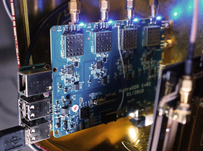
Over the last few months we've been working on a 4-input coherent RTL-SDR called 'KerberosSDR' (formerly known as HydraSDR) that is designed to be a low cost way to get into applications such as RF direction finding, passive radar, beam forming and more. It can also be used as a standard 4-channel SDR for monitoring multiple frequencies as well.
Phase coherent RTL-SDRs have been worked on and demonstrated several times over the past few years, but we've been disappointed to find that so far there hasn't been any easy way to replicate these experiments. The required hardware has been difficult to build and access, and the software has been kept as unreleased closed source or has been too complicated to install and use. With KerberosSDR we aim to change that by making phase coherent applications easier to access and run by providing ready to use hardware and software.
Thanks to our developer Tamás Peto, a PhD student at Budapest University of Technology and Economics whom we hired via the ad in our previous post, and the Othernet (formerly Outernet) engineering team who are our partners on this project, we've been able to build a working system, and demonstrate coherent direction finding and passive radar working as expected (demo videos below). We plan to eventually release Tamás' code as open source so that the entire community can benefit and build on it. Also if KerberosSDR turns a profit, we plan to reinvest some of the profits into continually improving the software and expanding the list of use cases.
KerberosSDR will be usable for coherent applications from ~80-100 MHz up to 1.7 GHz (as a standard receiver it will work down to 24 MHz like a regular RTL-SDR). The lower coherent limitation is due to the phase calibration board, and could be improved by custom creating a larger calibration PCB.
At the moment we are finalizing our prototype, and plan to begin final production within the next 2-3 months.
If you have any interest in KerberosSDR, please sign up to our Kerberos mailing list.
Direction Finding
KerberosSDR can be used to find the bearing towards a signal using it's coherent direction finding capabilities. The software by Tamás currently implements several direction finding algorithms such as Bartlett, Capon, Maximum Entropy (MEM) and MUSIC. In the video below we show a quick test of the direction finding system working with a HackRF being used as a signal source, and four dipole antennas connected to KerberosSDR in a linear array. The MUSIC algorithm is used.
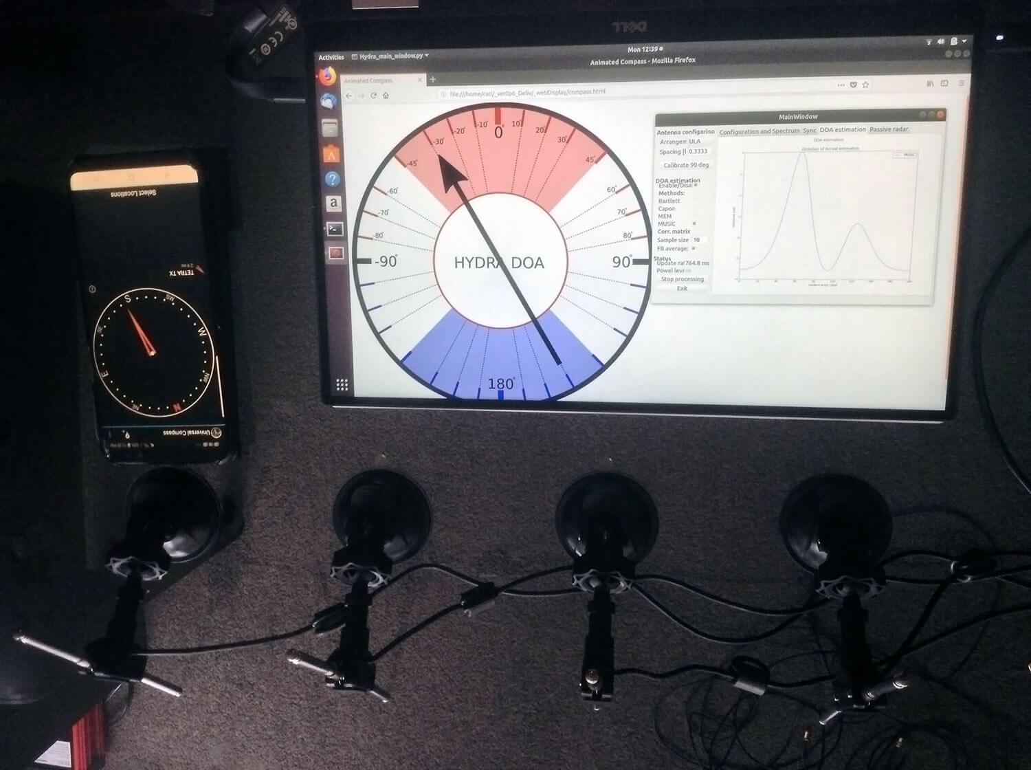
In the image below we also attempted to find the direction towards a known TETRA transmitter. We were able to confirm the direction with an Android compass app that points towards the known transmitter location. As the two angles match, we can be confident that Kerberos is finding the correct direction to the transmitter.
Passive Radar
KerberosSDR can also be used for passive radar. Normal radar systems work by transmitting a pulse of RF energy, and listening to the reflections from objects like planes, cars and ships. Passive radar works by using already existing transmitters such as those for FM/TV and listening for reflections that bounce of objects.
With a simple passive radar system you need two directional antennas and two coherent receivers. One antenna points at the transmitting 'reference' tower, and the other at the 'surveillance' area where you want to listen for reflections. It's important to try and keep as much of the reference signal out of the surveillance antenna as possible, which is why directional antennas like Yagi's are used.
The result is a doppler vs time delay graph, where the reflection of aircraft, cars, ships and other objects can be seen. The doppler gives you the speed of the object relative to your antenna and the transmitting tower, and the time delay gives you the distance relative to your antenna and the transmitter tower.
Below is an example time lapse video of KerberosSDR being used for passive radar. The reference antenna points towards a DVB-T transmitter at 588 MHz, and the surveillance antenna overlooks a small neighborhood, with aircraft sometimes flying over. The antennas we used were two very cheap TV Yagis.
You can constantly see the reflections from vehicles at small doppler values (low speeds), and every now and then you see an aircraft reflection which shows up at much higher doppler (speed) and further time delay (distance) points.

More information about KerberosSDR
KerberosSDR includes:
- 4x Coherent R820T2 based RTL-SDR dongles with standard 24 MHz - 1.7 GHz frequency range
- On board GPIO switched wide band noise source for sample sync and phase calibration
- Special phase calibration PCB for 4x inputs. Required to make the Kerberos phase coherent.
- On board USB Hub, so only one USB port is required on the PC
- Shielded metal enclosure
KerberosSDR can also be extended to 8x receivers by daisy chaining two boards together, so that their clocks and noise sources are connected. We've also taken into account undesirable effects such as heat related PLL drift which can be an issue for phase coherence.
At the moment we are also investigating whether singleboard computers like the Raspberry Pi 3 or Tinkerboard can be used, and there will be a header available for powering them via the Kerberos PCB. In the future we also plan to work on optimizing the code and potentially using CUDA/OpenCL GPU optimizations for passive radar so everything runs smoothly.
Once released we plan to have extensive tutorials and documentation that show exactly how to set up and replicate direction finding and passive radar experiments with low cost antennas.
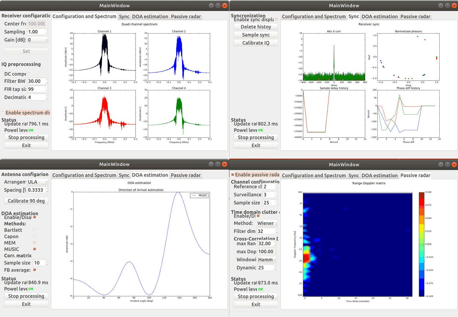
Screenshots of KerberosSDR software:
Remember, if you're interested please sign up to the KerberosSDR mailing list for announcements and the chance to get in early with the cheaper first 100 units.
Be on the look out for more interesting demos that will be posted in the coming weeks!
[the_ad id="14114"]
Update: Please note that due to a Trademark complaint, we have changed the name of this unit from HydraSDR to KerberosSDR.
KerberosSDR Updates: 27 August 18
This week we've managed to get the KerberosSDR demo software made by Tamás Peto functioning on a TinkerBoard. The TinkerBoard is a US$60 single board computer. It's similar to a Raspberry Pi 3, but more powerful. We've also tested the app running on the Raspberry Pi 3 and Odroid XU4. The Pi 3 is capable of running the software but it is a little slow, and the Odroid XU4 is a little faster than the TinkerBoard. In the future we hope to further optimize the code so even Raspberry Pi 3's will be smooth.
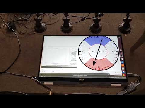
In the video below we used a circular array of four whip antennas connected to KerberosSDR. The TinkerBoard is connected to KerberosSDR and is set up to generate a WiFi hotspot, which we connect to with an Android phone and a Windows laptop. The Windows laptop connects to the TinkerBoard's desktop via VNC, and the Android phone receives an HTML/JavaScript based compass display via an Apache server running on the Tinkerboard. With this setup we can wirelessly control and view information from KerberosSDR and the TinkerBoard.
We've also tested the KerberosSDR system on a real signal, and have found it to work as expected. More demo's of that coming later.
For more info on KerberosSDR please see our previous announcement post.
KerberosSDR Updates: 4 September 2018
In this post we'll show an experiment that we performed which was to pinpoint the location of a transmitter using KerberosSDR's coherent direction finding capabilities. RF direction finding is the art of using equipment to determine the location of a transmitting signal. The simplest way is by using a directional antenna like a Yagi to try and determine the bearing based on signal strength. Another method is using a pseudo-doppler or coherent array of antennas to determine a bearing based on phase information.
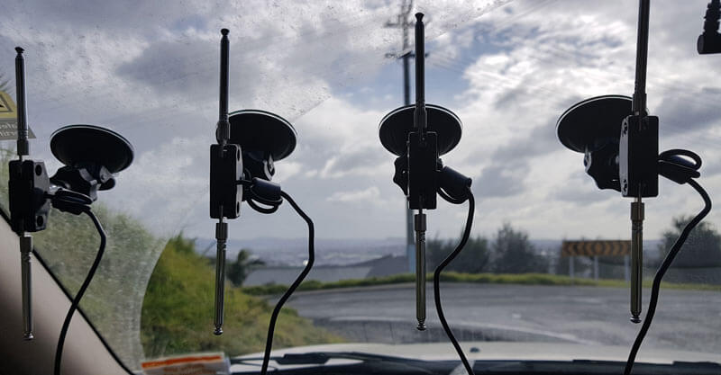
For the test we tuned the KerberosSDR RTL-SDRs to listen to a signal at 858 MHz and then drove to multiple locations to take direction readings. The antennas were set up as a linear array of four dipole antennas mounted on the windshield of a car. To save space, the dipoles were spaced at approximately a 1/3 the frequency wavelength, but we note that optimal spacing is at half a wavelength. The four dipole antennas were connected to KerberosSDR, with a laptop running the direction finding demo software.
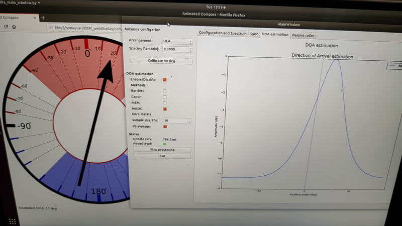
Our open source demo software (to be released later when KerberosSDR ships) developed by Tamás Peto gives us a graph and compass display that shows the measured bearing towards the transmitter location. The measured bearing is relative to the antenna array, so we simply convert it by taking the difference between the car's bearing (determined approximately via road direction and landmarks in Google Earth) and the measured bearing. This hopefully results in a line crossing near to the transmitter. Multiple readings taken at different locations will end up intersecting, and where the intersection occurs is near to where the transmitter should be.
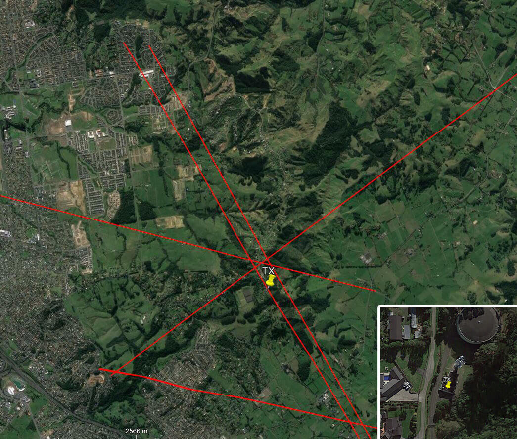
In the image below you can see the five bearing measurements that we made with KerberosSDR. Four lines converge to the vicinity of the transmitter, and one diverges. The divergent reading can be explained by multipath. In that location the direct path to the transmitter was blocked by a large house and trees, so it probably detected the signal as coming in from the direction of a reflection. But regardless with four good readings it was possible to pinpoint the transmitting tower to within 400 meters.
In the future we hope to be able to automate this process by using GPS and/or e-compass data to automatically draw bearings on a map as the car moves around. The readings could also be combined with signal strength heatmap data for improved accuracy.
This sort of capability could be useful for finding the transmit location of a mystery signal, locating a lost beacon, locating pirate or interfering transmitters, determining a source of noise and more.
KerberosSDR Updates 7 September 2018
For this test we parked our car to the side of a highway and pointed a cheap DVB-T Yagi antenna towards a DVB-T transmission tower, and another cheap Yagi down the road. The video shown below displays the results captured over a 5 minute period. The blips on the top half of the display indicate vehicles closing on our location (positive doppler shift), and the blips on the bottom half indicate objects moving away (negative doppler shift).


The resolution of each individual vehicle is not great, but it is sufficient to see the overall speed of the highway and could be used to determine if a road is experiencing traffic slowdowns or not. When larger vehicles pass by it is also obvious on the display by the brighter blip that they show. The display also shows us that the highway direction coming towards us is much busier than the direction moving away.
In the future we'll be working on optimizing the code so that the display updates much faster and smoother. It may also be possible in the future to use the third and fourth tuners to obtain even greater object resolution.
KerberosSDR Updates 27 September 2018
In this post we're showing some more passive radar demos. The first video is a time lapse of aircraft coming in to land at a nearby airport. The setup consists of two DVB-T Yagi antennas, with KerberosSDR tuned to a DVB-T signal at 584 MHz. The reference antenna points towards a TV tower to the west, and the surveillance antenna points south. Two highlighted lines indicate roughly where reflections can be seen from within the beam width (not taking into account blockages from mountains, trees etc).
The second video shows a short time lapse of a circling helicopter captured by the passive radar. The helicopter did not show up on ADS-B. On the left are reflections from cars and in the middle you can see the helicopter's reflection moving around.
We are expecting to receive the final prototype of KerberosSDR within the next few weeks. If all is well we may begin taking pre-orders shortly after confirming the prototype.


Can we network multiple units together for more accurate Direction Finding?
I would like to have one set up on out tower site, base station and mobile vehicle for good triangulation.
I now own 4 KerberosSDR devices, 2 of them are connected to Tinkerboard-S and 2 of them are running on RasPi3-B+
I also want to network them so we can geo-locate a ‘jammer’ more quickly and accurately. We think we may have an intentional repeater jammer (for our ham radio repeaters) and we’re worried he may be mobile. The only way to geo-locate a mobile jammer in a timely manner is to use a few stationary RDF sites that are networked together – and of course networked to a mobile KerberosSDR just for ‘last mile’ geolocation.
Check out our new post about networked DFing, might be useful https://tinyurl.com/uwze6yh. If you get any results with it please let us know.
I love you guys!!!
I’ll go there and check it out.
You realize this is going to make everybody go out and buy more KerberosSDRs just to tinker with this?
bonjour
très interessant, mais est-ce que cela fonction sous windows10?
bonne continuation.
I bought 2 KerberosSDR’s and I bought a Tinkerboard S and a Raspberry PI 3+ to use each with.
I was going to connect them with a short USB to MicroUSB cable, but then I noticed that the Tinkerboard and Pi will ‘fit’ directly onto the KerberosSDR’s board via the 40-pin header bar. When you remove the enclosure bottom there’s even instructions on the board next to the 40-pin header bar that say:
“Please remove JP2 jumper for Raspberry Pi operation”
“Power booth KerberosSDR and RPi fromUSB PWR.”
Will this work with both the Pi and the Tinkerboard?
What are the drawbacks?
What is the production and shipping status at this time?
I was looking at your setup for passive radar. I use an RTL-SDR dongle for AIS on my sailboat. It was nice to see traffic and the circling airplane on your tests. But in both scenarios you and the reference signal was stationary. In a sailboat the reference signal will be stationary but the boat will be moving. Albeit under 9 MPH but course changes would be an issue. If using Yagi antennas one would have to change the aim of the antenna if the boat tacked onto a different course. Has it been tested at all in this type of scenario? With Omni directional antennae?
Is it possible to use Downconvertor to get it find directions for higher freqvencies above 1.7 ghz?
As long as the received phase difference is maintained. So multiple down converters with a common lower jitter reference clock from all of them and using equal cable lengths in each to maintain the phase difference.
Hi
I am also interested in this. Just to be clear on what your answer means.
Is it possible to give a better reference to the board as it is?
What is the tuning range of the receivers?
Thanks!
Christo
The first question I do not know for sure, but there appears to be a U-FL connector marked “CLK_I/O” on the top right of the board.
That is in the article above search for “1.7 GHz” which is only mentioned twice.
Wondering if there is an external clock capability to refine into a GPSDO system?
Would be interesting to couple the position and clock information from a GPS for both functions.
Thank you!
It’s stated in the write-up that the RPi3 is a little slow for this application. Was a 32 bit OS being used on the RPi3 at the time? If so, would it be worth trying a 64 bit OS on the RPi3 for a performance improvement? This one here seems quite stable and versatile..
.. and offers both CLI and GUI versions.
In my experience it out-performed the 64 bit RPi3 openSUSE image that was released around the same time.
I will test that 64-bit OS this week and see if it brings any improvements.
Unfortunately the 64-bit OS’s don’t seem to work. The one linked doesn’t work on the 3B+, but I found another one here that https://github.com/Crazyhead90/pi64. It installs fine, but scipy simply won’t install on it for some reason, it just crashes the Pi at some point during the either a manual compilation, or installation via pip3. Anyway, with recent optimizations, the code appears to be fast enough for DFing ong the Pi3B+ now. Passive radar only updates at about 0.5fps, but we can’t expect much more from the Pi3.
I appreciate you taking the time to try this, thanks! I incorrectly assumed the older pi3b was being used in testing, rather than the newer pi3b+, sorry to send you down the garden path.
Perhaps this 64bit OS here would be more useful:
https://github.com/sakaki-/gentoo-on-rpi3-64bit
I have no experience with this particular distro but it appears to be suitable for the pi3b+ and may work better than the previously suggested distro for this application.
This particular 64bit OS has shown considerable improvements (~30-40% in some use cases) over the 32bit alternatives – see paper here:
https://www.researchgate.net/publication/319433633_Raspberry_Pi_32_Bit_and_64_Bit_Benchmarks_and_Stress_Tests
Regardless, great to hear that the pi3b+ now produces good results using the 32bit OS!
Very interested in building a unit with Raspberry Pi if proving out. Presently have Byonics DF and working on Rashawk . Bruce P, Smith, LtCol., Civil Air Patrol, Florida Wing SAR Officer
Hi. Do you ship to military intallations such as APOs? Thanks.
Yes APOs are no problem.
I’m not ready to pay by my CC. Is it possible to pay by Paypal ?
There are devices used in vessels called sattelite compass, those devices have a set of gps antenas (2 or 3) mounted in a line or triangle set, usually mounted permanently on a mast. They compute the signals from the three antenas and are able to find the heading of the vesel like a magnectic compass, but instead of using earth’s magnectic field it uses GPS signals. I read some time ago that they do that by calculating the fase diference on the received signals.
Could such a task be accomplished using kerberos as a receiver?
You would need external filters and externally powered LNA’s (no Bias-T) to be able to receive GPS. But if you have the required hardware to be able to see signals from the GPS satellites then, on paper at least, I don’t see why not with a large enough spacing between the antennas.
Sounds possible, but at the moment you’d need to look into writing your own code for that application.
Greetings. I am very interested in the KerberosSDR for DF and remote sensing applications like passive radar as well as other non-coherent applications like monitoring and recording several radio channels simultaneously. I plan on using Linux based software for these purposes and I plan on making my setup mobile, that is to say laptop based. I notice that in the KerberosSDR Direction Finding Test youtube video that the laptop being used is a Dell and it appears to be running an Ubuntu based Linux distro. For compatibility’s sake I’d like to know what model Dell laptop was used in these tests, I’d like to try to acquire that same model for use in my setup or if you have a different make/model you would recommend that plays well with Linux, I’d love to hear your thoughts. Thanks.
It’s a DELL XPS13 2-in-1, but really any relatively modern laptop/computer will work…I can say installing Linux dual boot on the DELL was not easy though. Modern laptops with SSDs can have trouble with Windows and Linux dual booting due to things like Secureboot, UEFI etc, plus I had to make unsupported changes to Windows drivers. But there are guides out there that can help.
I´m planning to buy five, any discount?
Sorry not at the moment while we’re in the preorder stages as that’s already the lowest price we can give. Maybe when it’s full price we can give some discount for multiple pcs.
Is the source code for the recent experiments currently available? It may perhaps accelerate development if it’s open to the community for contributions.
We plan to release the open source code in December once we start shipping.
How great would it be if someone started a website where folks could network and share their KerberosSDR (w/GPS) as a resource to create a networked direction-finding system. We’ve had some guys in our area intentionally jam radio repeaters. It would be nice to ‘DF’ them instantaneously based on multiple lines of bearing (LOBs).
In fact, couldn’t we also do it with regular ‘single’ RTL-SDRs using signal strength like the KiwiSDR does it?
It’s possible that you could indeed set up multiple fixed position KerberosSDRs and have them each provide bearings for automatic pinpointing.
BTW, the KiwiSDR doesn’t use signal strength, it uses TDoA (time difference of arrival) which is different.
I’m interested in using this for falconry – tracking the transmitters attached to birds. Currently the transmitters I use are 216MHz. I DF using a 5-element yagi and offset attenuator, which works pretty good – would like to see if this is any better.
I suddenly find myself needing to think about an RFP for an imaging riometer, which would be based on an NxN array of antennae, with beam synthesis.
What are the possibilities for “ganging” these things. In my case, ‘N’ could be as large as 8…
My own use-case would be radio astronomy. My suspicion is that I’d need to integrate their sample-alignment algorithms into my code, which isn’t a huge deal, but it’s not as nice as having hardware that is just inherently capable of doing N-channel coherence…
Sounds interesting. Can you elaborate a little bit on your specific use cases?
I know a lot of RA occurs at HF. The minimum frequency of the R820T2 is 24 MHz, but the calibration board we’ll provide is probably only going to work down to around ~80 – 100 MHz (basically it’s a directional coupler). But for lower frequencies it shouldn’t be too difficult to print a larger calibration board, or increase the noise power with an external noise source. For lower HF frequencies a 4x upconverter running from the same clock might work.
The sample alignment code should also be able to be easily implemented into other code bases.
Actually, most RA occurs at VHF and above. The long wavelengths below VHF make high-gain antenna a tad awkward, and the ionosphere is partially opaque even up to 50MHz or so.
Both simple two-antenna interferometry, and beam-forming are things that are of interest to our little enterprise: http://www.ccera.ca
We do have “more exotic” SDR hardware, but if we can do coherence relatively cheaply, it mans we can consider more projects where coherence is a necessity…
-Marcus
Have you tested the range of the calibration now? Will it work up to 1.7 GHz?
Very neat!
I can’t say I’d have any use for the direction finding or radar features. However having more tuners in one device should hopefully make for a smoother, more compact trunk tracking experience. Maybe even have the ability to monitor two trunked systems at once!
what about the Rock64?
Rock64 would work too, but the TinkerBoard is probably more powerful for this application.
I see an Android phone showing a Line Of Bearing (LOB) display in one of your photos. Will there be an Android interface for this device? That would be so useful.
The Android phone is just for comparing the DoA signal bearing with a magnetic bearing of the known location. But the code is running well on a Tinkerboard and Odroid XU4. With those single board computers it’s possible to create a WiFi hotspot, and VNC into the desktop to view and control the GUI on an Android phone. It’s also possible to use web server software to make the HTML based arrow display accessible via a browser on your Android device.
Cuando el soft de utilizacion, sea en Windows,seria interesante para mi.
can you tell us more about the trademark complaint? I couldn’t find any existing hydra sdr with a quick google and us patent office search.
They haven’t registered in the US, only in their own country, but they have registered the .com domain. Probably no legal requirement to change, but if it’s going to be confusing i’d rather change now than have problems down the line.
Danny VK6DVR
Tracking meteor trajectories:
I wonder how good this HydraSDR system would be at reporting the trajectory of meteors, but more particular, the much larger bolides, some of which create a sonic boom as they enter the earth’s atmosphere, and a trajectory could help with the approximate ground impact location if they survived without a total burnout.
VK6DVR Danny Robinson | VHF Weak-signal & Meteor-Scatter on 6-Metres | Perth, W.Australia
This could indeed be an interesting use case. With 2 receivers on passive radar you get relative speed and distance. With more it should be possible to get more information like a bearing. At the moment we’re only going to support 2-RX passive radar, but possibly more in the future if we sell enough to fund further dev work, or someone else contributes to the open source code.
This would be a fun application! Reminded me of a paper I saw some time back about passive radar imaging of meteor trails. I had to go dig it up!
https://www.haystack.mit.edu/edu/reu/2013/files/2013_SohbatzadehPresentation.pdf
This would be a fun application! Reminded me of a paper I saw some time back about passive radar imaging of meteor trails. I had to go dig it up!
https://www.haystack.mit.edu/edu/reu/2013/files/2013_SohbatzadehPresentation.pdf
And This one on Hackaday: https://hackaday.com/2015/06/05/building-your-own-sdr-based-passive-radar-on-a-shoestring/
Perhaps you can apply direction finding to meteor skip or broadcast stations.
Damn this looks cool. Eagerly awaiting more news!
very interested and the $99-$150 price tag is reasonable. I’d be willing to pay for the $150 now and to Beta test the HydraSDR and provide feedback!
is the application for windows ?
It’s a Linux app.
The screenshots look like something built in GnuRadioCompanion. Is this the case? Also, has there been any consideration to release a 2-receiver version, or at the very least to make the DoA app compatible with only 2 of the receivers active to make it easier to run on low-end PCs?
Regardless, very, very excited to hear about this, and look forward to ordering!
Thanks! GNURadio isn’t involved in the code, it’s all based on Python and C.
We’ve just confirmed that the 4-RX DF system works at a decent speed on the $60 Tinkerboard singleboard PC, so any PC with hardware roughly equivalent to that should be able to run it just fine. It also works on a Pi 3, but it’s a bit slower than we’d like at the moment. We’ll be working on optimizing the code at a later date too, so the speed may improve. A 2-RX system wouldn’t be very good as there are increased ambiguities with less receivers.
So how does one know if they are actually signed up for the mailing list without any form of confirmation after hitting the button?
After pressing submit you should have received a ‘double opt-in’ email from Mailchimp (due to GPDR regs). You click on the confirmation in that email, and it should let you know that you’re signed up.
One potential application not mentioned here might be coherent averaging to reduce noise and improve SNR. With 4 SDRs the potential SNR gain is something like 6 dB, although the actual would depend on implementation.
This might be useful for people who are listening for fairly weak signals (although ideally I suppose one would have an LNA and then a four-way splitter, or four separate antennas with 4 separate LNAs).
Is this an application that HydraSDR might someday support?
Yes we’re considering applications like beamforming, averaging, noise suppression etc too. But remember it’s still an RTL-SDR, so we’re probably not going to be marketing this as a high end DX device.
Would be great if you could use it for 2.4 ghz wifi. Would the chip be able to do that with some cooling?
The EOL(end of life) Rafael Micro R820T2 tuner is already being driven outside of specification
The R820T/T2 official frequency range from 42 Mhz to 1002 MHz.
But everyone who uses it for SDR has managed to get the PLL’s to lock from ~24 MHz to ~1.7 GHz.
There is no trickery that can get that tuner chip to operate at 2.4GHz. Maybe if they used a R848 then possibly, but it would need major of testing and there would be a lot of bashing of heads, weeping and gnashing of teeth and even then it may not work, and the overall performance would be lower.
Unfortunately the R802T2 can’t tune that high, no amount of cooling would help. Possibly in the future some sort of cheap downconverter for WiFi could be developed, but we’d need to look into several things to maintain coherency.
I am interested, but after reading MailChimp’s privacy policy, I am not signing up to their mailing list after reading through their privacy policy. It is basically agreeing to allow them to spy on you “Information we collect from other sources: From time to time, we may obtain information about you or your Contacts from third-party sources, such as public databases, social media platforms, third-party data providers and our joint marketing partners. We take steps to ensure that such third parties are legally or contractually permitted to disclose such information to us.” The more of it I read the less I want to use their service.
Mailchimp is probably the largest mailing list provider out there. I think what they’re talking about is one option in their admin panel where you can enable a paid premium option that uses the email to look up your *public* social media data, to get information like age/gender/location etc. Same as if someone put your email address into Google and tried to see what they could find. We’re not using that option.
I’m sorry but no, any marketing company that describes itself as providing “cutting-edge marketing technology” and being the “world’s largest marketing automation platform” and also describe their activity as “highly profitable”, ARE tracking people online.
And by explicitly getting people to actually opt-in, they avoid being listed on the usual marketing opt-out websites, which assumes that everyone wants to have their online activity tracked, unless they explicitly say that they do not want that browser to be tracked:
http://www.youronlinechoices.com/
http://optout.aboutads.info/
http://optout.networkadvertising.org/
LOVE IT!
interesting, will keep an eye on it.
can you give us a price estimate?
We’re expecting it to be somewhere between $99 – $149 + shipping. It should work out to be cheaper or similar to DIYing the hardware.
That’s pretty reasonable. Definitely interested if it works out.