Simple NOAA/Meteor Weather Satellite Antenna: A 137 MHz V-Dipole
Over on his blog Adam 9A4QV (seller of various RTL-SDR related goods including the LNA4ALL) has just made a post detailing a build of a high performance super simple NOAA/Meteor M2 weather satellite antenna. Most antenna designs for polar orbiting weather spacecraft are based on circularly polarized turnstile or QFH designs. However, Adams antenna is based on a very simple linearly polarized dipole, which makes construction almost trivial.
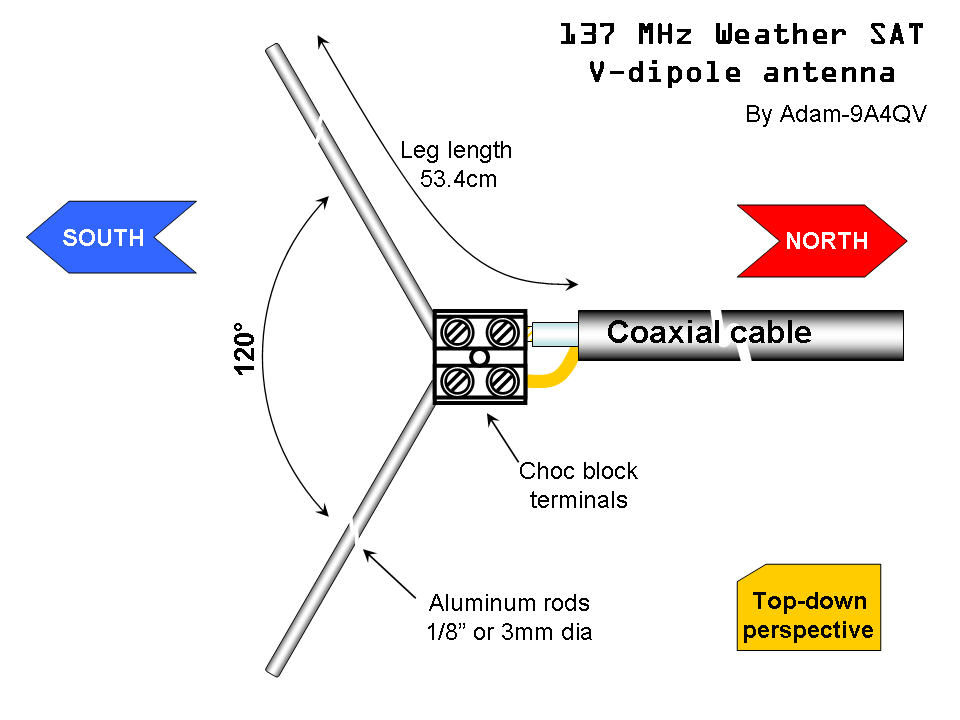
The idea is that by arranging a dipole into a horizontal ‘V’ shape, the radiation pattern will be directed skywards in a figure 0 (zero) pattern. This will be optimal for satellites travelling in front, above and behind the antenna. Since polar orbiting satellites always travel North to South or vice versa, we can take advantage of this fact simply by orienting the antenna North/South.
There is also another advantage to Adams design. Since the antenna is horizontally polarized, all vertically polarized terrestrial signals will be reduced by 20 dB. Most terrestrial signals are broadcast in vertical polarization, so this can help significantly reduce interference and overloading on your RTL-SDR. Overloading is a big problem for many trying to receive weather satellites as they transmit at 137 MHz, which is close to the very powerful FM broadcast band, air band, pagers and business radio. In contrast a circularly polarized antenna like a QFH or turnstile only reduces vertically polarized terrestrial signals by 3 dB.
As the satellites broadcast in circular polarization there will be a 3 dB loss in Adams design from using a linear polarized antenna. But this can be considered as almost negligible. Adam also argues that the home construction of a QFH can never be perfect, so there will always be at least a ~1dB loss from inaccurate construction of these antennas anyway.
The final advantage to Adams design is that construction is extremely simple. Just connect one element to the center coax conductor, and the other to the shield, and spread apart by 120 degrees.
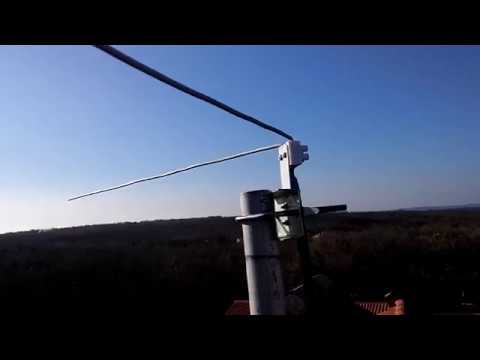
Adam has tested the antenna and has gotten excellent results. If you want more information about the antenna design, Adam has also uploaded a pdf with a more indepth description of the design and his thoughts.


If I add a reflector how far below the aerial does it need to be ??
and does it need to be connected to the coax shielding ??
Regards, Dave
or connected to ground ??
Dave
Hi ! After adjusting the length of the legs, can this dipole be used successfully for AirScatter (Plane Scatter) or ADS-B reception ? Thanks
Just found this post I have an RTL-SDR dongle on way I have ordered the antenna kit would the telescopic antennas work for this? if so where do i measure the 53.4cm from
Thanks
Glen
Measure the distance from the point where the coaxial cable wires are separated to the tip of the antenna. But I think in reality a few cm either way doesn’t really make that much of a difference.
I bought replacements telescoping antennae from Aliexpress for $1.50 each and worked fine!
I did the same thing. I’ve got telescopic antennae and I am pretty sure I sized them correctly. However, the signal quality is really bad. It seems like I am only getting good detail while the satellite is straight overhead, but there are very big chunks of just noise above and below that little stripe of good signal/noise. Any tips? What directions are the legs of your antenna pointing in?
I have also been having some trouble. Lately, only 50% of my passes are good. I might have a problem with the soldered connections to the antennae. Yes, I really only get good images for passes that are almost overhead, probably because my antennae are mounted on a stick only a couple of meters high that I take out to a field (I live in an apartment building so can’t mount on the roof.) Noise can be caused by obstructions like buildings and trees. I face the antenna south. I also have a Nooelec Sawbird Filter and Preamp set for NOAA frequencies.
It may be worth checking your co-axial cable for water ingress. I always seal the end of cables with contact adhesive or hot melt glue, not not silicone which is corrosive to copper and aluminium.
Try mounting antenna at a different heights from the ground, that is 50cm, 1m, and 3m, there’s a very good youtube video somewhere when a guy explains different radiation patterns for dipole antenna at a different height. Apparenlty it has something to do with the signal reflection, so you might find a “sweetspot” somewhere closer to the ground
Adam 9A4QV actually has a video on his Youtube channel explaning this exact effect.
Link got lost in the last one: https://www.youtube.com/watch?v=zEW4YRChyF4
“137 MHz V-dipole noisy bar problem explained”
One thing I didn’t see mentioned in the article (unless I somehow missed it): If you are in the SOUTHERN hemisphere, the antenna needs to be rotated 180deg – so that the “choc block” is at the SOUTH, not north end. For experimenting, I just used an off-the-shelf “rabbits ear” antenna mounted horizontally and the elements opened up to 120deg, and got surprisingly good results for NOAA satellites!
Hi Mick, sorry for replying/commenting so late on this, which side of the equator you are situated should not make any difference, the NOAA birds are traveling north to south wherever you are in the World,direct the antanna accordingly. It does not matter if you are either side of the equator. I may well be incorrect, Please straighten me out on this.
You’re right, the v-dipole radiation pattern is (theoretically) symmetrical. It shouldn’t make any difference whether the open end is pointed north or south. If someone does see a difference, their antenna probably has an imperfection somewhere.
Or, as in my case, there may be a degree of shielding in one direction. In my case I have high hills to the north east, and a building on the slope to the north. Raising an antenna to the height to clear these would be totally impractical, it would need to be about 500ft.
Where can one buy the 1/8″ aluminum rods?
Home Depot or most hardware stores or you can go to https://www.onlinemetals.com/ or other online retailers.
Also its used for TIG welding 😀
where can you buy choc block terminals? or are these constructed?
You can buy them at home depot, they are really called screw terminals. https://www.homedepot.com/p/1-0-STR-to-14-AWG-Dual-Rated-Type-ASR-ALCUL-Splicer-Reducer-with-Solid-Barrier-Wire-Stop-2-Pack-ASR1114-B2-10/100126602 here is a link, they call them splicer reducers, how confusing
I know his is old, but in case anyone else has this question, 6 or 8awg wire bare copper wire is also a good option.
What do you mean by “flat star-wise pattern”?
Probably the reflector looks like in this image: https://bit.ly/2JARMw8
Thanks
Hello I want to do this projest but I a have question. Do the alluminium rods need to be hollow or solid?
Thanks in advance!
Good question. I would think it doesn’t really matter but I would use solid rods for best results
Thanks
You don’t want or need solid core for Antennas. Solid rods are heavy they need more support and are pointless.
Mine are solid and i am happy with the device.
Doesn’t matter at all.
Sorry if this is a newbie question, but I am wondering how is the V-dipole connected to the coaxial cable? Thank you for the help in advance!
If you read the article it tells you? The article even draws a picture for you!
Like I noted above, I bought replacement telescoping antennae from Aliexpress that were meant to replace the antenna on a boom box . They are lightweight and are capable of extending to beyond the 54 cm needed. They were attached at the base to a small plate with a pivot. Thee plate had a predrilled hole which I used to screw down the antenna and the pivot allowed me to adjust the two to have the 120 degree spacing.
I now am getting much better pictures having tightened and fixed my connections, but the best pics are direct passes. Passes at 45 degrees and lower are so so.
This antenna works like a charm on NOAA, Meteor-M2 and ISS. It works even better if you add reflectors below the V-dipole: six of the same rods you used for the antenna, each rod 54.5 cm length, fitted in a flat star-wise pattern mounted about 27.25 cm below the V-dipole. This creates a reflective ground plane and improves reception notably.
But even without the reflectors, this is a great and very easy to build antenna.
I’m curious to get more detail about the reflector. Specifically, what “star-wise” pattern looks like.
Thanks!
Sorry if this is a newbie question, but I am wondering how is the V-dipole connected to the coaxial cable? Thank you for the help in advance!
Use a piece of plastic terminal block. One side for the two rods the other side the center and screen of the coax cable
I managed to build the antenna properly, I can receive radio signals 😀 . I would like to ask you, Do I need an LNA to receive SSTV from ISS? At first I didn’t think it was necessary but then I saw one guy was using one of them and then doubts came up. In that case, which one do you recommend me? Thank you for the help in advance!
You could but really it’s such a strong signal even on a handheld scanner it’s not necessary imo. If you wanted to though apparently the uptronics LNA is a good one
https://store.uputronics.com/index.php?route=product/category&path=59
Hi again! I was not lucky with the reception… I was able to receive the carrier but not continuously… I just build the antenna with 4mm diameter aluminium rods (Altough this only affects BW doesnt it?) and then correct the length for 145,8 MHz… I just connect the coaxial cable directly to rtl-sdr via an adapter… Any ideas what can be wrong? Thank you for the help again!
Why “correct” for 145.8 MHz when the satellites are transmitting at 137-138 MHz?
What do you mean by “flat star-wise pattern”?
Hi, how did you count all the values. I have 6 mm rods. How should the length be one leg/arm :)?
Hello there!I build this antenna two weeks ago and placed it on my house,a reflector is mounted about 50 cm under the dipole.The reflector is about 65 cm and looks like two turnstile antennas,like a star.In the past i build many antennas for noaa reception,but this one gets the best reception.And i just use a simple radio scanner,not a noaa receiver.The reception is just amaizing.Greetings from germany
Thank you for your tutorial, I built mine with 3/8″ aluminum rods and can pickup the satellite at -1.7 elevation on my building and getting 35 dB signal levels, great images! Thank you again!
Wow I’d like to see some images with such low elevation. Please join and post on Facebook groups like APT group. weather satellite images or noaa weather fax
somebody can help? I have this good antenna, but I want to know if the WxtoImg software runs well in Windows 10?. I tried to find where is the place (link) into de web page of the software where I can upgrade it but I can not find it. Other suggestion of software for pick up the wx images from NOAA?.
Tanks! de Jesus xe2kaf
http://www.wxtoimg.com/
The latest stable version is 2.10.11.
2017 Standard Edition Upgrade Key
Install in Help -> Enter Upgrade Key (use upper/lower case exactly as below):
Full Name: WXtoImg Standard
Email Address: your email address
Upgrade Key: TYLQ-KGKT-7M73-U86U-EAQ2
I try this but pop up tell me invalid Key…
Update 7/30/2018 the website to download WXtoIMG has been restored.. The software for most platforms is available. Includes a working Professional Upgrade Key.
https://wxtoimgrestored.xyz/
Special thanks to: adinbied
add /beta to the URL get the version that runs on Windows 10
Hi! What if I invert the positive and negative on cable? Sorry if it’s a newbie question.
It will make no difference.
sorry, observing your scheme the antenna is oriented to the south …. can you confirm?
Yes, the antenna faces south. it also works really well if you put it on a pole and aim it at the satellite as it passes. Holding the antenna so the dipole faces the ground (and almost touching the ground) works for me when the satellites are at a max elevation of 20° or less 🙂
Here’s today’s NOAA-19 passes: https://twitter.com/orpen_m/status/962756945508798465
sorry, did you use a preamp? …
hi
thanks for all
how polarized antenna?
1) S >| N
or
2) S |< N
Works great. I alter some conditions to make it a little bit easier for indoor and test it. Find my results here on YT:
https://youtu.be/daqL7U3USo8
Hello,
I tried your antenna but it does not work! … I did not detect any signal (RF carrier) when I passed the satellite.
I used the coaxial TV / SAT as a cable.
I would appreciate your suggestions, thank you.
I would suggest that you have another problem. This type of antenna, a dipole, was first used by Senator Marconi, and also by Sir Oliver Lodge, millions of amateur radio operators use half-wave dipoles from 1.6MHz up to UHF frequencies, cut to appropriate lengths. I have used such an antenna for radio work since 1969, for amateur radio, satellite and military work. Check your connections first, make sure your antenna is clear of obstructions (it needs to be outdoors and clear of buildings). Check your frequencies and the times of satellite passes.
Hello,
I wanted to ask you, how do you calculate the 120 degrees? …. thanks for the reply.
Actually I just guessed at it really which is not hard to do…90 deg being obvious…so another 3rd of that say with a clock hands 9 to 1 o’ clock roughly !
Hey guys so I have been trying to get images from the NOAA sats and METEOR for days now. I built a QFH performance is not good so I built this antenna. Performance in the same spot as the QFH… Not good. Moved the antenna away from my house I get great signal. Trying to figure all this out, I had both antennas mounted about 20 feet off the ground and about 6 feet away from my house. I would have to almost aim both of them for them to get any kind of signal. But away from the house the V-Dipole works great. How high do I need to get this thing. Also can I use RG6 Coax which is 75 ohm over 50ohm. RG6 is on the QFH and i got a 50ohm on the V-Dipole.
6 ft is not really far away enough from the house. Try right down the garden on a parasol base with a telescope pole from 1st direct pools… a v pole will never bring in as much signal as a QFH or crossed dipole as I use but if it’s positioned correctly it’s an amazing antenna but you must use 3mm rods each one being 53cm in length
I’ve built a couple of these antennas and they are great considering how quick they are to build. I do have a consistent problem with one of the channels inverting depending on which direction they are passing and wondered if anybody has any thoughts?
NOAA-19 Southbound and both 18 & 15 Northbound have the A channel inverted. The image is white where it should be black — including the sidebar.
The MCIR image looks OK, but wxtoimg cannot generate MSA, HVC or HVCT images because of the inverted A channel.
The waveform also looks wrong on screen. Instead of an inverted v shape with a strong central peak, I get an M shape which also takes up more bandwidth than it should do — suggesting that the signal is out of phase.
Adjusting the V angle, length and which terminals the coax feeds makes no difference.
Any ideas how I can fix this?
Hmm. Interesting. This isn’t because the satellites were over unlit ground, is it? I know the A channel switches to a different sensor that’s mostly white when the satellite passes over unlit areas (night). I’ve just built one myself, I have an incoming southbound NOAA-18 pass in about an hour, and a northbound NOAA-19 pass in three hours, so I will update then.
Nope, no issues here. I believe it’s just due to the satellite switching sensors.
Alex, thanks for the info — I thought I was doing something wrong 🙂
It also explains why NOAA-19 inverts the A channel as it heads towards Iceland at the moment.
Cheers.
The underlined bit mentioning a pdf isn’t working as a link, if in fact that is what it is. Where can I find the more in-depth info mentioned to be in that pdf?
Seems to be working just fine here. It’s a dropbox pdf link but doesn’t require an account.
Any chance you can show us a link to one of the choc blocks that will accommodate the 1/8″ aluminum? the ones I see here in the states, on Amazon, are all too small and won’t accommodate a wire/ rod that thick.
thank you
Hi Adam,
Will this work with 2.5 mm insulated solid copper wire?
YES!!
Just connect right to the antenna? No need for a balun?
IMHO add a simple choke balun by winding the cable will help with the radiation pattern.
at 137 Mhz I think the choke should be around 4 turn of 3″ of diameter if the cable is not too thick.
I did a better job then guessing the size of the balun.
with this calculator http://hamwaves.com/antennas/inductance.html
a good choice is D=107mm N=2 l=80 d=4, this coil resonate at ~137Mhz
I was going to use some thin aluminum tubing from an antenna. Would I need to change the length of the tubing or something else because of the bigger diameter?
Not for receiving, no. For transmitting though, there would be an end-correction. Usually a nice large diameter makes the antenna more broadbanded.
Very, very good performance from two pieces of wire as an antenna. Thank you very much for sharing. ?dl=0
?dl=0
Here is the image I got yesterday:
I got my RTL USB yesterday.
This afternoon, I built your antenna, and no later then this evening, I was able to get 2 perfect IR-Channel Pictures. Many thanks for this excellent tutorial!!!
Links to those 2 pictures:
https://ibb.co/igd01F
https://ibb.co/iKJuTv
and I got this with no previous experience, neither with SDR, nor with any satellite receptions…
Wow! Great images and experience. I’m going to try this antenna today! Thanks for the comments.
Here’s one that I captured last Saturday:
https://ibb.co/iuARva
Hello Adam,
So this is a really nice piece of work. We are also trying to get signal from NOAA satellites. After recieving signal, we need to calculate doppler shift and deduct orbital parameters from that.
My question is, can this be achieved with this V-Dipole antenna design? Also we were able to find 4mm dia rods, would that have big impact on this design?
Thanks for help in advance.
Hi i Built this antenna with 4mm rod and its working pretty well , i have 22 metres of mini 8 coax and at the moment the V dipole is 8 feet off the ground and i have just realised its pointing the wrong way .. its total build cost was £4ukp .. .aprox $5.50
Built and tested this antenna. It works really well while sticking out of my window, so I can’t even imagine what would be the performance if I get it high in open area.
How should we protect this antenna against ESD?
The simplest way is to use the 1 Mega-ohm resistor across the dipole on the choc block. At some point (before reaching the receiving equipment) the braid/coax should be grounded.
More advanced is using the quarter wavelength shorted coaxial stub, also across the dipole on the choc block.
This stub can notch some frequencies and if we chose smartly the length we can kill the strong blockers. At some point (before reaching the receiving equipment) the braid/coax should be grounded.
Can you elaborate a little on placement? Like put it across the 2 poles?
Hi can anyone give me some extra information on the calculation used?
Particularly where the constant 147 is derived from. Many thanks!
L(m) = 147 / F(MHz)
L(m) = 147 / 137.5
L = 1.068 m = 106.8cm
Each leg = 53.4 cm
I have no idea where that number came from but if you put 137MHz into a frequency to wavelength calculator ( e.g. http://www.1728.org/freqwave.htm ) you get 218.83 cm. And a quarter of a full wavelength is ~54.7 cm. I’m interested as well where the 53.4cm came from.
velocity factor difference – depends on what material you use to build it with.
147 is half the speed of light reduced by 2% correction factor for thick wires
It’s very similar to the formula US hams are taught and tested on, which is L = 468/f. Where L is dipole length in feet.
Granted there is a slight difference here of a couple of percent, probably because 468/f is usually used for thin wire antennas at HF and is a bit conservative (assumes a slowdown of 5 percent rather than 2)
http://www.kb6nu.com/468-ham-radios-magic-number/
In either case the basic premise of both is that the speed of light depends upon the medium.
Thanks everyone. Clear answers. Anyway I’m planning to make this design with thin aluminum (diam 0.8cm) tubing I have lying around. Would there be other values for the correction factor? Can you recommend a resource to look these things up?
Hello Anna,
you can try the following link for the simple approximation:
http://www.radio-electronics.com/info/antennas/dipole/length-calculation-formula.php
As a rule of the thumb, bigger diameter will give you more usable bandwidth. I did measure the RL and using the 1/8″ aluminum stiff wire from the video I have 20db RL for the 5MHz BW. On the resonant frequency the RL is 40dB+. For the 10db RL the BW is 24 MHz and I use the same antenna without problems on Aeronautical AM band as well as HAM 2m band. The antenna is working nice also on the government/military band 140-143Mhz where the fighters flying 200km away can be heard loud and clear.
With a slight modification, would this be usable for receiving amateur satellites on the 2M band as well as weather satellites?
Hello Martijn,
This antenna is not good for the amateur satellites. Usually, HAM sats are not 3 axis stabilized and they are thumbing. Combined with the low power and linearly polarized antennas on the sats you will experience a deep fading (QSB) on your side. Directional antennas with tracking are required for descent operation.
You can get a fraction of transmission from that satellites using the V-dipole but this will be rather frustrating experience.
Forgot the most important, you will need circular polarization directional hi-gain antennas.
Hi Adam,
Thanks for your help. Due to the space needed and complexity of a directional antenna with a tracking rotor, this won’t be a option for me. I had a small hope that this simple setup will do. 😉
Another one trying to fill up a 1.5L bottle with 2L of water 🙂
It can be done but this is completely another antenna / topic.
Not needed. Not too plug a manufacturer – but Arrow makes the most cost affordable for purchase/retail dual band hand held yagi antenna for shooting (amateur) starfish – albeit kinda fun to make a DIY version, the cost actually turns out to be almost the same in parts acquired/needed as you actually end up with quite a bit of spare aluminum in just making a single unit. Plus the
Arrow one is significantly, lets say *well built*, robust and completely tuned. They were the whopping 45$ USD last time I checked.
I like this approach. I saw it on Adam’s blog yesterday before this was posted.
Although it may not be perfectly optimal in theory, in practice it may yield better results because it is very easy to build and tune (I haven’t even attempted to tune my QFH because I don’t have a modern VHF VNA (I have an antenna analyzer but it’s an old analog one — basically a fancy grid-dip-meter — that only works for HF) and besides it would be a real pain anyway to change the dimension of loops!!!).
The bill of materials is very simple — two linear elements (I might try using solid 14ga. copper wire rather than aluminum), something to act as a center insulator (choc block, piece of plasic with holes drilled out, whatever) and a choke balun (couple of snap on ferrites maybe).
I have been going crazy trying to work with circularly-polarized antennas, but the thing is NOAA signals are actually pretty strong; 3db shouldn’t matter terribly much; and the biggest problems are terrestrial interference and actual mechanical failure of the antenna. I suspect there are a number of ways where a mistake in a circularly-polarized yagi or QFH could easily result in a 3db loss of performance, or worse.
So anyway, kudos for the “KISS” approach to antenna design.
Adam,
Can you show/draw exact scheme in PAINT,
how exactly did you connect cable to aluminium rogs or Chock Block?
Regards,
Alex
Hello Alex,
the choc block has two screws on each terminal. Under one of the screws the aluminum bar is inserted and under the other screw of the same terminal the coaxial cable wire (center or braid). Same goes for the other choc terminal. Once you do that you can spread the wires to create the 120deg angle. Of course, it will look much better if you prepare the wires and bent the ends before inserting into the choc terminals.
Thanks Adam.
Very informative.
But still some misunderstand as new to this .
1)We have one coax cabel,it goes to first terminal where it then connected to aluminum bar.?Right?
2)But how another aluminium bar in second terminal is connected to the cable?
We need to solder one more cable between coaxil cable and put it under screw of second terminal?
3)Can I connect coaxial cable directly to RTL SDR , via BNC-SMA adapter ,without any dc block between them?
Thank you in advance
1) Yup
2)Center conductor is screwed or soldered to one terminal, ground/outer conductor is screwed/soldered to 2nd terminal.
3) you can, I think he put that there to help protect against transient currents on the coax, in other words, to prevent a sudden surge in voltage which would fry the front end of the rtlsdr.
thanks
I’m a retard. The blocking capacitor is there because his RTLSDR has the bias-T mod enabled. He’s protecting the dongle from any potential shorts since there was no LNA in line in the initial test.
Yes, this is the reason why I have a DC-block in line without LNA. You never know what may happen on the antenna so better protect dongle from short if the Bias-T is enabled.
Very interesting. However I think some kind of balun would improve the radiation pattern simmetry and avoid picking noise from the coaxial braid. You could either use a winding of a few turns of coaxial next to the feed point working as current choke or a half wave coax balun for feeding the dipole arms in oposite phase. In the later case, it also transforms the impedance in a 1:2 ratio.
A balun to improve the symmetry as suggested to prevent the currents on the braid can improve the things even more. This may be added but the design is more complicated for the beginners. Impedance transformation is not required, the impedance is very close to 50 ohms using a V-shape and the match and RL is good, up 30 dB. I do have the the RL plots but did not want to complicate with this details as they are not so important for this purpose.
The idea was to present a simple antenna that will deliver good results with minimum efforts and using cheap materials.
I mean 1:4 impedance transformation.
Incorrect: A turnstile has no vertical component. Both elements are horizontal with respect to the ground (same as Adam’s V-dipole), so the discrimination is far greater than 3dB for terrestrial vertically polarized signals.
Every antenna has a vertical component. Infinite cross-polarization exists only in theory. Cross polarization between V-H or RHCP-LHCP should be infinite, but we can see that in practice it is from 20-30 dB. You can sheck that just turning your whip antenna for 90 degrees. Just in theory you can have only one component. How come then the turnstile is receiving the signals from horizon? This signals are coming from a very low elevations. In theory you should not have any signal, but in practice the signal is present.
Received signals from the horizon (on a v-dipole or turnstile) are still primarily using a horizontal component. Read my comment again – I am not disagreeing with you, but saying that the vertical component of a turnstile vs the v-dipole is the same – in theory infinite, but like you say, in practice, more like 20-30dB down (that’s why I say “far greater than”). My point is that the post above is incorrect in saying that a CP turnstile only attenuates vertical signals by 3dB.
The main concern and the problems are the strong signals coming from the Airplanes just 10km above and they are using the vertical polarization (mentioned in the full PDF article) If you have a circular polarization, the vertical component is not coming just from the horizon, but from direction with higher elevation. The other problem is that some professional services and mainly the WBFM transmitters are also using the circular polarization in the areas with the terrain with hills and valleys where due to multiple reflections the transmitted signal change the original polarization. Such a reflections may result with deep fading in signals due to cross polarization (30dB). To avoid this problems the WBFM is transmitting circular polarization and the theoretical fading should be not more than 3dB.