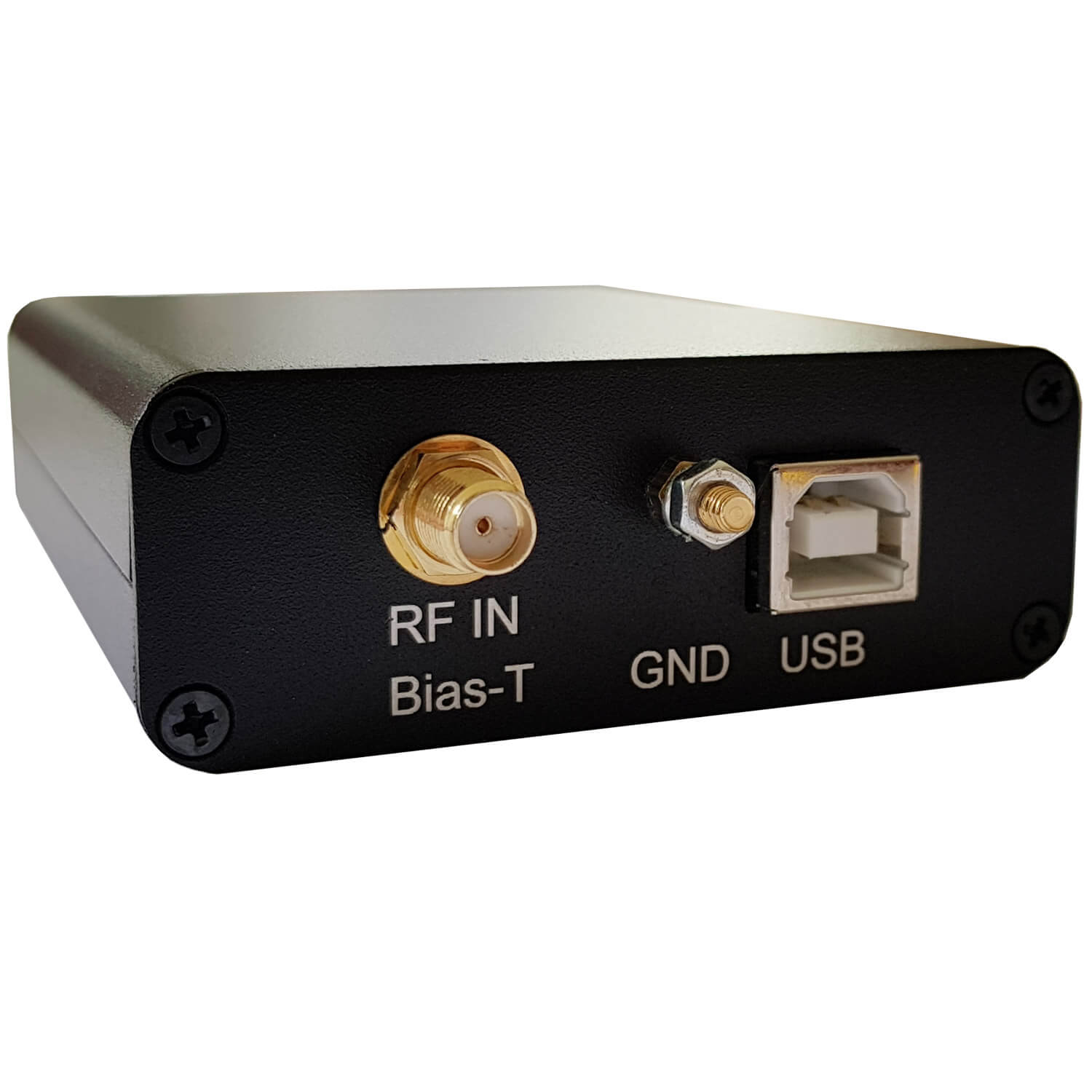
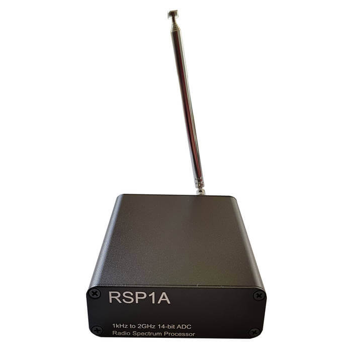
Over on our store we've just released two new products for sale. The first is a metal case upgrade kit for the SDRplay RSP1A. It is similar to the previous enclosure that we sold for the RSP1, but no longer comes with an included BCFM filter since the RSP1A has this filter built in as a software switchable option.
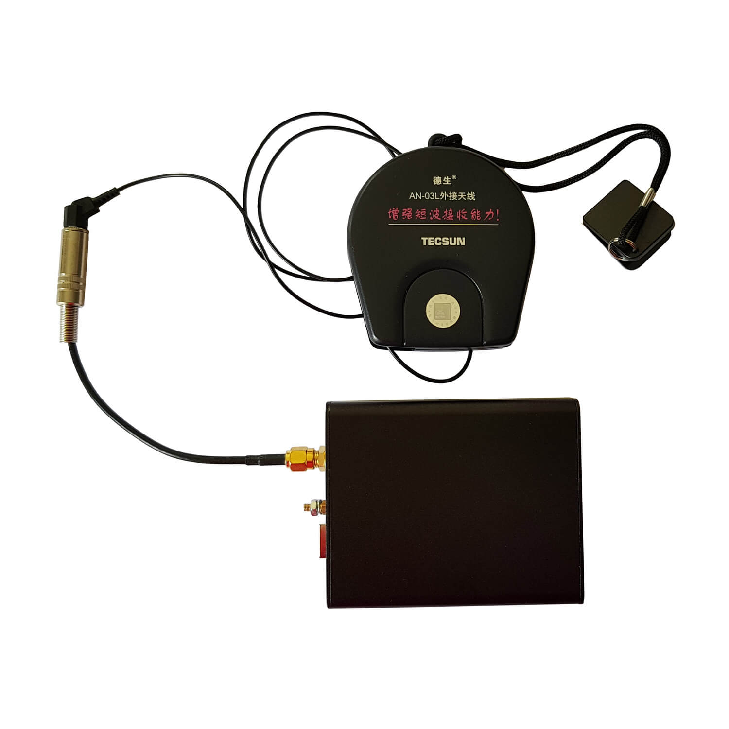
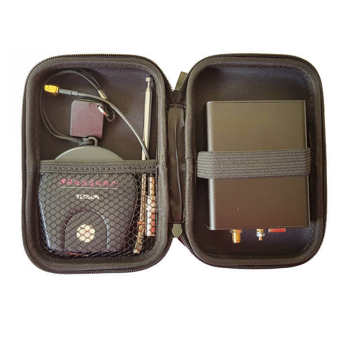
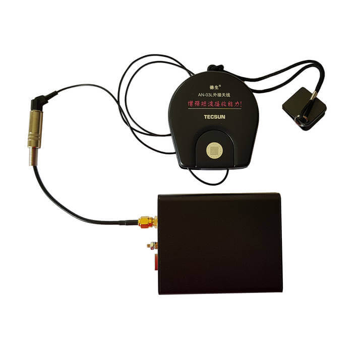
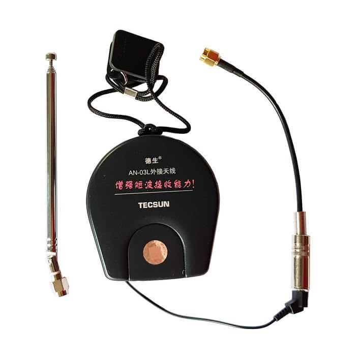
Instead we've included a portable 7 meter (23 feet) long wire antenna spool (Tecsun AN-03L) with SMA adapter, and an 11 cm to 48 cm adjustable SMA telescopic antenna. The 7 meter antenna is great for HF SWLing, and neatly rolls up into the spool for travelling. The telescopic antenna is a portable VHF/UHF antenna that can plug directly into the SMA port of the RSP1A. Both antennas fit neatly into the supplied semi-hardshell carry case. The set costs US$29.95 including shipping and is available on our store, and will be on US Amazon in a couple of weeks.
The second product is the portable antenna set just by itself. The set includes the 7m Tecsun AN-03L antenna spool, the mono plug to SMA adapter and the 11 cm to 48 cm telescopic antenna. It can be used on any SDR with SMA ports. The set costs US$11.95 and is also available on our store. It will also be on Amazon in a couple of weeks.
Over on our store we've just released two new products for sale. The first is a metal case upgrade kit for the SDRplay RSP1A. It is similar to the previous enclosure that we sold for the RSP1, but no longer comes with an included BCFM filter since the RSP1A has this filter built in as a software switchable option.
Instead we've included a portable 7 meter (23 feet) long wire antenna spool (Tecsun AN-03L) with SMA adapter, and an 11 cm to 48 cm adjustable SMA telescopic antenna. The 7 meter antenna is great for HF SWLing, and neatly rolls up into the spool for travelling. The telescopic antenna is a portable VHF/UHF antenna that can plug directly into the SMA port of the RSP1A. Both antennas fit neatly into the supplied semi-hardshell carry case. The set costs US$29.95 including shipping and is available on our store, and will be on US Amazon in a couple of weeks.
The second product is the portable antenna set just by itself. The set includes the 7m Tecsun AN-03L antenna spool, the mono plug to SMA adapter and the 11 cm to 48 cm telescopic antenna. It can be used on any SDR with SMA ports. The set costs US$11.95 and is also available on our store. It will also be on Amazon in a couple of weeks.
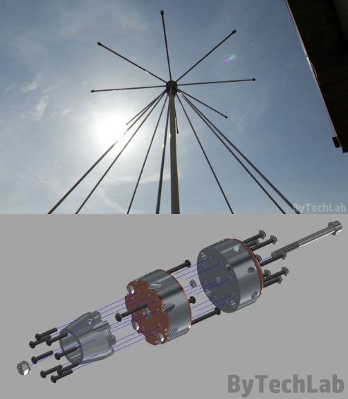
Over on his blog author ByTechLab has posted about his 'mostly 3D printed' discone antenna. A discone is a type of wideband antenna, so it is commonly used with SDRs like the RTL-SDR that have huge frequency ranges. Building a discone can be difficult, but ByTechLab shows that with a 3D printer it is possible to print the aluminum rod mounts, which significantly reduces construction complexity. His post shows the exact directions, and the stl files are available over on Thingiverse.
Note that back in March we saw another 3D printed discone by mkarliner that used a full cone design with the cone being made out of aluminum tape. Discones based on aluminum rods should however be more weather resistant, and more able to withstand wind loads, so ByTechLab's design is more suitable for permanent outdoor mounting.
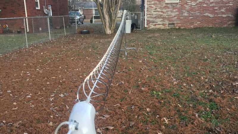
A slinky is a fun little toy that is essentially a long and loose spring. You can perform tricks with them, but the most iconic use is making them walk down stairs all by themselves. Over on Hackaday we've seen a tutorial that shows how to use a slinky as a good antenna for the 80m (3.5 MHz) band. Using a slinky as an antenna is nothing new to hams, but the original post on imgur shows some pretty clear photos and instructions on how to construct one.
The text written by the original poster on imgur notes that he uses this antenna very successfully with his RTL-SDR in direct sampling mode and this even outperforms his regular shortwave radio. He notes that slinkies aren't weather proof, so some sort of weather proofing spray coating or oil might be useful for a permanent set up.
If you are interested apart from the discussion on Hackaday there is also a comments thread on Reddit where the original poster discusses what he purchased.
Over on our store we now sell our dongles with a receive only dipole antenna kit that replaces the older magnetic whip style antennas from the previous kit. This was done for a few reasons
We believe that the dipole kit is much more versatile and will enable beginners to get better reception straight away
Magnets of any type are difficult to ship as they are not allowed by many airmail carriers.
While the magnetic whip still works perfectly fine, the dipole kit should make it easier to get the antenna outside or in a better position away from noisy computers/electronics, and it also allows for a simple v-dipole configuration for satellite reception.
The units are currently in stock at our Chinese warehouse either bundled with an RTL-SDR or as an individual antenna set.
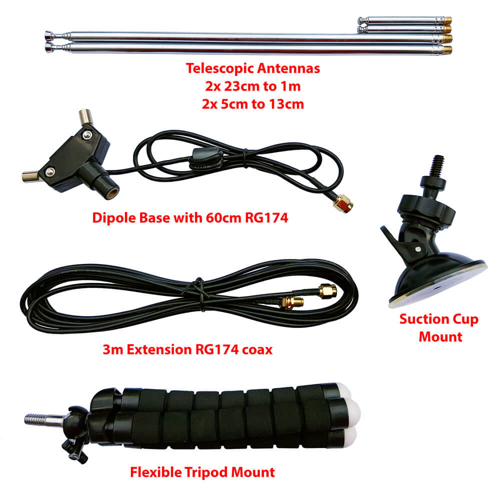
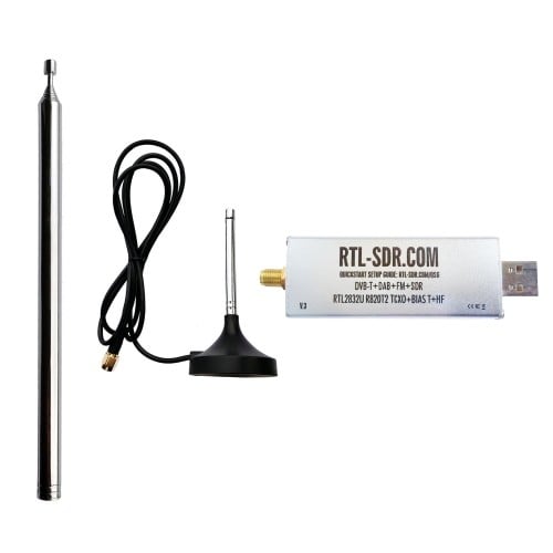
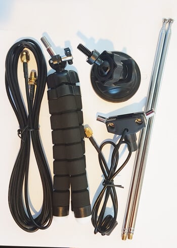
This post is a guide on how to use the dipole antenna set in various configurations. First we'll show and explain about what's included in the set:
1x dipole antenna base with 60cm RG174 cable and SMA Male connector. This is the dipole base where the telescopic antennas connect to. The short run of RG174 is decoupled from the base elements with a ferrite choke. This helps to prevent the feed line from interfering with the dipole radiation pattern. The dipole has a 1/4 inch female screw on the bottom, which allows you to use standard camera mount products for mounting.
1x 3 meter RG174 coax cable extension. This coax cable extension allows you to mount the antennas in a place that gets better reception. E.g. outside on a window, or higher up.
2x 23cm to 1 m telescopic antennas. The telescopic dipoles are detachable from the dipole base via a M5 thread which allows for greater portability and the ability to swap them out. These long telescopic antennas cover VHF to UHF.
2x 5cm to 13cm telescopic antennas. These smaller antennas cover UHF to 1090 MHz ADS-B, and even still work decently up to L-band 1.5 GHz frequencies.
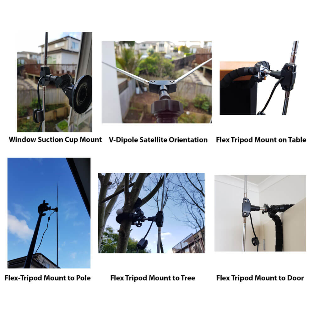
1x flexible tripod mount with 1/4" male screw. This piece allows you to mount the dipole on a variety of different locations. E.g. a pole, tree branch, desk, door, window sill. The legs of the tripod are bendy and rubberized so can wrap securely around many objects.
1x suction cup mount with 1/4" male screw. With this mount you can mount the dipole on the outside of a window, on a wall, car roof/window, or on any other smooth surface. To use first clean the surface with window cleaner or isopropyl alcohol. Then place the suction cup on the cleaned surface and close the lever to activate the suction.
What's included in the new Dipole kit
Dipole Orientation
Signals are normally transmitted with either horizontal, vertical or right hand/left hand circular polarization (RHCP/LHCP). This is essentially the 'orientation' of a signal, and an antenna with the same polarization should be used too for best performance. A dipole can be used in either vertical or horizontal polarization, just by orienting it either vertically or horizontally.
If you mismatch vertical and horizontal polarization or RHCP and LHCP you'll get an instant 20dB loss. If you mismatch vertical/RHCP, vertical/LHCP, horizontal/RHCP, horizontal/LHCP you'll only get a 3dB loss.
For vertical polarization, in theory it does not matter which way around you orient the antenna as long as it's vertical. However in practice, you may get slightly better results by having the element connected to the center coax conductor pointing UP. You can confirm which element is connected to the center conductor by temporarily removing the black lid on the dipole base (it can be easily pried off with a nail or flat head screwdriver).
There are also ways to optimize the radiation pattern with dipoles. For example for LEO VHF satellites you can use a V-dipole configuration. You can also make a somewhat directional antenna by using a bent dipole configuration. Some more examples of dipole configurations can be found on KK4OBI's page on bent dipoles.
Terrestrial Signal Reception
Most signals broadcast terrestrially (on Earth) are vertically polarized.
To use the dipole for vertically polarized signals, all that you need to do is orient the elements vertically (up and down).
In theory there is no up and down for the dipole when used in the vertical orientation. However in practice you may find slightly better performance when the 'active' element points up. The active element is the one connected to the center conductor. You can check which element is connected to the center conductor by removing the top cap on the dipole base. This will let you look inside at the connections.
Satellite Reception
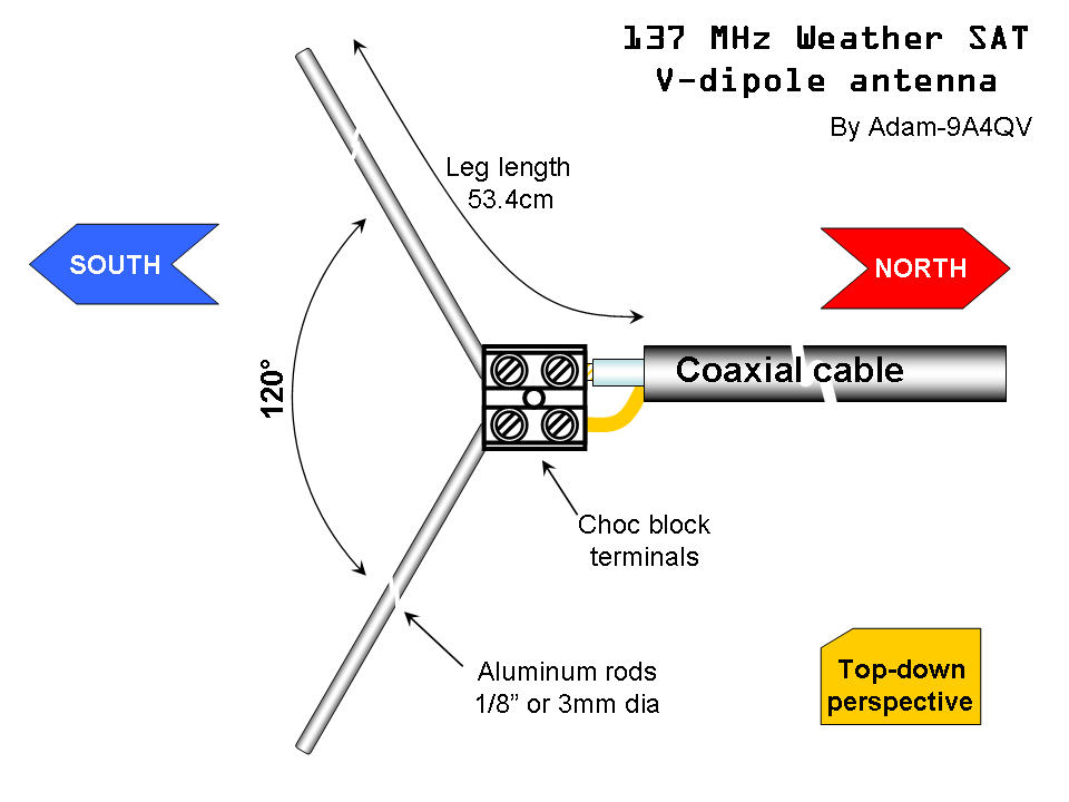
The dipole can be used in a V-Dipole configuration for polar orbiting satellite reception. See Adam 9A4QV's post where he wrote about how he discovered that it was possible to use dipoles in this configuration for excellent satellite reception. The idea is to use the dipole in horizontal polarization. This gives 3dB loss on the RHCP satellite signals, but also nicely gives 20dB loss on terrestrial signals which could be overloading your RTL-SDR.
For 137 MHz satellites like NOAA and Meteor M2 extend the larger antenna elements out to about 53.4 cm each (about 2.5 sections). Angle the dipole so it is horizontal and in a 'Vee' shape, at about 120 degrees. Place the dipole in the North-Source direction.
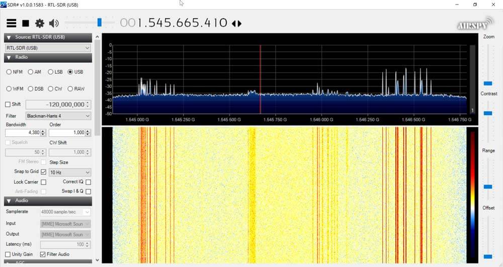
With an appropriate L-band LNA like the Outernet LNA the dipole can also somewhat work to receive L-band satellites. Using the smallest antenna collapsed, use a V-dipole configuration and point it towards the L-band satellite. Ideally use a reflector too. In the image below we used a simple cookie tin as a reflector. A hole was drilled into the center and the mount used to clamp in the antenna. This together with the Outernet LNA was enough to receive AERO and STD-C.
Choosing the Antenna Element Length
Like with the whip you can use an online calculator to calculate the optimal length for your frequency of interest. We recommend this dipole calculator. The exact length does not matter too much, but try to get the lengths as close to what the calculator says as you can. With the dipole you want both elements to be the same length.
In reality extending the antenna to almost any random length will work just fine for most strong signals. But if you're really trying to optimize those weak signals you'll want to fine tune the lengths.
Basically the longer the antenna, the lower it's resonant frequency. The shorter the antenna, the higher the resonant frequency. You want to be close to the resonant frequency. Remember that there is about 2cm of metal inside the antenna itself which needs to be added on. Below is a cheat sheet for various lengths and frequencies. Note that the length refers to the length of one side of the dipole only (e.g. the length that you need to extend each element out to).
Large Antenna, 5 Sections, 100cm + 2cm is resonant @ ~70 MHz
Large Antenna, 4 Sections, 80cm + 2cm is resonant @ ~87MHz
Large Antenna, 3 Sections, 60cm + 2cm is resonant @ ~115 MHz
Large Antenna, 2 Sections, 42cm + 2cm is resonant @ ~162 MHz
Large Antenna, 1 Section, 23cm + 2cm is resonant @ ~ 285 MHz
Small Antenna, 4 Sections, 14cm + 2cm is resonant @ ~445 MHz
Small Antenna, 3 Sections, 11cm + 2cm is resonant @ ~550 MHz
Small Antenna, 2 Sections, 8cm + 2cm is resonant @ ~720MHz
Small Antenna, 1 Section, 5cm + 2cm is resonant @ ~1030 MHz.
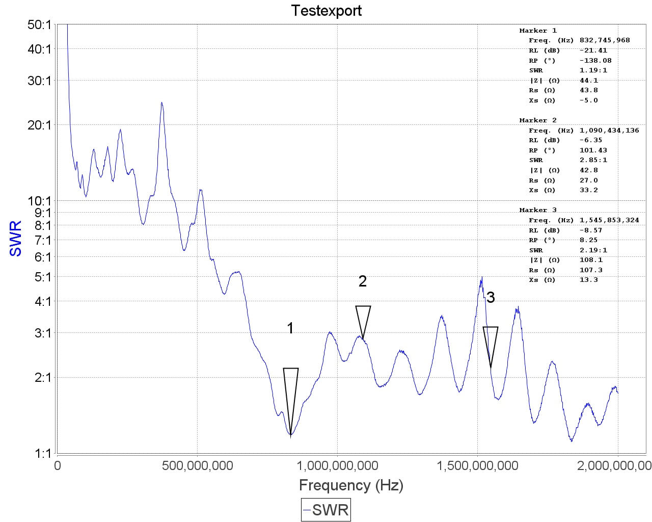
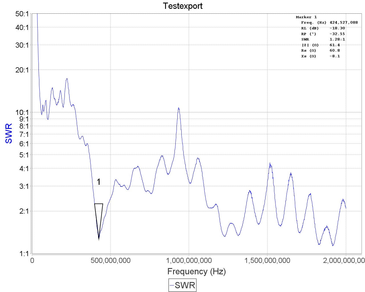
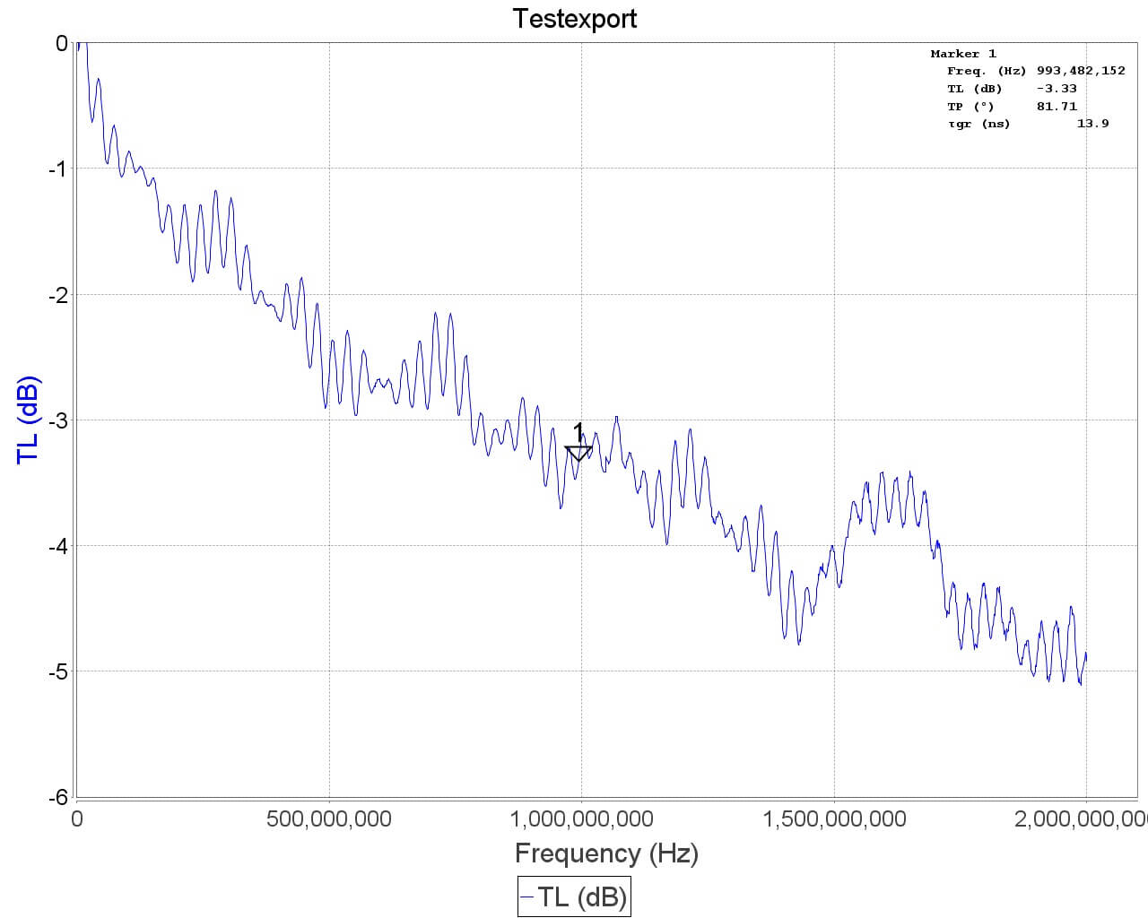
See the SWR plots at the end for a more accurate reading of the resonance points. But in most cases no matter what you extend the length to the SWR should be below 5 at most frequencies which results in 2.5 dB loss or less. More accurate info on VSWR loss graphs can be found in this document from the ARRL "Understanding SWR by Example" (pdf).
Using the Mounts
The suction cup mount allows you to easily place the antenna on a window, or any smooth surface. To use it first clean the surface thoroughly with isopropyl alcohol or glass cleaner. Then apply the suction cup and close the lever to lock it in place. The lever requires some force to push down, and this ensures a strong grip. You can then angle the antenna in the orientation that you need using the ball socket. Once in place close the ring to lock the ball socket in place.
The flexible tripod mount is useful to mounting the dipole to almost everything else. Including tables, doors, poles, trees etc. The legs of the tripod have a flexible metal wire inside and rubber sheath so they can be bent into a position to grip almost anything.
Some examples of how to use the mounts.
Note that the mounts and RG174 extension allow you to more easily use the dipole antennas outside or in a better indoors position (e.g. on a Window). But please note that like our older magnetic whip we do not recommend permanently mounting this antenna outdoors. This antenna is designed to be a portable antenna that you put up and take down at the end of the day - not for permanent outdoor mounting. It is not protected against water, not grounded so cannot handle a lightning strike and could be damaged with dirt and grime build up. For permanent outdoor mounting you could conceivably fill the inside and hinges of the dipole with silicon putty or maybe even hot glue and ground the antenna yourself, but we have not tested this. The stainless steel antennas won't rust, but dirt and grime could gum up the collapsing mechanism.
Tightening the hinge
Once you've got the orientation of the dipoles the way you want, you might want to tighten the hinge so the elements don't move so easily anymore. To do this simply take a small screwdriver and tighten the screw on the hinge.
ESD Bleed Resistor
Note that our older antennas had a 100kOhm ESD bleed resistor between the two elements. This is no longer the case on newer models. The purpose of the resistor was to slowly bleed any ESD buildup to ground.
We decided to improve ESD protection on the dongle instead, so the ESD bleed resistor is not longer required and is now omitted on newer productions.
Sample VSWR Plots
Other Notes
Note that this is NOT an antenna designed for TXing. It is an RX antenna only. So please do not TX with it unless you really know what you are doing as you could damage your TX radio.
Apologies for the long out of stock period, we sold out of our remaining Amazon US stock almost immediately a few weeks ago due to a large Reddit thread which popularized the Reddit /r/rtlsdr forums (a big welcome to any new RTL-SDR users!). Amazon is currently processing the new stock and it should be ready to ship out in a few days.
We also have a new antenna set in the works which should be ready for purchase in a few weeks. This antenna set is essentially a custom modified TV dipole with mounting kit. The kit will contain:
1x Telescopic Dipole Antenna base with 20cm RG174 cable
2x removable 22cm to 1M telescopic antennas
2x removable 5cm to 13cm telescopic antennas
1x 3M SMA RG174 extension cable
1x suction cup window mount
1x bendy tripod mount
Antenna Base
The telescopic antennas mount onto the antenna base via a screw, so they can easily be removed and interchanged between the large and small ones, or packed away for storage.
The dipole antenna base attaches to the suction cup or bendy tripod mounts using a 1/4″ camera screw. So any cheap camera mounting accessories like clamps, tripods etc can be used to mount the dipole as well.
The coax cable on the base also has a ferrite core choke on it to help decouple the feedline from the antenna, and there is a 100kOhm bleed resistor added to reduce static discharge.
Mounts
The included suction cup mount allows you to mount the dipole on a window (ideally outside) and orient it into a vertical, horizontal or V-Dipole position. The bendy tripod allows you to use the antenna on your desk, folded over a door, on a tree branch, pole, or anywhere that the tripod legs can be wrapped around.
Usage
The biggest problem that new RTL-SDR users face is the antenna. Most are starting off with a mag mount whip, and have no way to mount them outside where they should be for better reception. Keeping them inside can cause poor reception and increased pickup of local interference from electronics. Our dipole with the mounts aims to solve this problem.
Using a dipole generally results in better reception than with a mag mount whip, and also allows for easier outdoor mounting. The 3M coax extension cable allows you to get the antenna at least to a window in your room.
Note that although we recommend using the antenna outside, please remember to take the antenna back inside when not in use to avoid lightning/ESD/weathering problems. It is not designed for permanent outdoor mounting and please remember that any permanently mounted outdoor antenna should have good grounding to protect your radio against ESD and lightning.
For general use we recommend using the dipole in the vertical orientation as most signals are vertically polarized. The dipole can also be used in a V-Dipole configuration for excellent VHF satellite reception, such as for NOAA/Meteor weather satellites. Just extend the telescopic dipoles to be as close as possible to resonant at the frequency of interest using this calculator. Getting the length perfect is not critical, and actually using any length will still receive something.
Apart from NOAA we’ve also tested the dipole with L-band satellites. Together with an LNA and the smaller telescopic antennas it’s possible to receive Iridium and Inmarsat signals. Reception is not as good as a patch antenna, but you can still get the stronger AERO and Iridium signals quite easily. If you add a reflector made out of a small cookie tin the signals can be boosted further, and this is enough to receive the weaker STD-C and Outernet signals.
Eventually this dipole set will replace the mag mount antenna bundled with the dongles currently. Target price is between $9.95 – $14.95 for the antenna set by itself, and $25.95 for the dongle + antenna set. We expect the antenna set to be ready for shipping in 2-3 weeks, and about 3-4 weeks for the dongle + antenna set. More details and usage examples will be shown nearer to the release.
Over on his blog Adam 9A4QV (seller of various RTL-SDR related goods including the LNA4ALL) has just made a post detailing a build of a high performance super simple NOAA/Meteor M2 weather satellite antenna. Most antenna designs for polar orbiting weather spacecraft are based on circularly polarized turnstile or QFH designs. However, Adams antenna is based on a very simple linearly polarized dipole, which makes construction almost trivial.
The idea is that by arranging a dipole into a horizontal ‘V’ shape, the radiation pattern will be directed skywards in a figure 0 (zero) pattern. This will be optimal for satellites travelling in front, above and behind the antenna. Since polar orbiting satellites always travel North to South or vice versa, we can take advantage of this fact simply by orienting the antenna North/South.
There is also another advantage to Adams design. Since the antenna is horizontally polarized, all vertically polarized terrestrial signals will be reduced by 20 dB. Most terrestrial signals are broadcast in vertical polarization, so this can help significantly reduce interference and overloading on your RTL-SDR. Overloading is a big problem for many trying to receive weather satellites as they transmit at 137 MHz, which is close to the very powerful FM broadcast band, air band, pagers and business radio. In contrast a circularly polarized antenna like a QFH or turnstile only reduces vertically polarized terrestrial signals by 3 dB.
As the satellites broadcast in circular polarization there will be a 3 dB loss in Adams design from using a linear polarized antenna. But this can be considered as almost negligible. Adam also argues that the home construction of a QFH can never be perfect, so there will always be at least a ~1dB loss from inaccurate construction of these antennas anyway.
The final advantage to Adams design is that construction is extremely simple. Just connect one element to the center coax conductor, and the other to the shield, and spread apart by 120 degrees.
Adam 9A4QV’s V-Dipole for 137 MHz Weather Satellites.
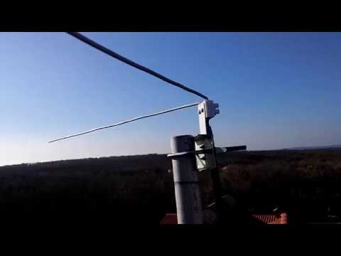
Adam has tested the antenna and has gotten excellent results. If you want more information about the antenna design, Adam has also uploaded a pdf with a more indepth description of the design and his thoughts.
DIY 137 MHz WX sat V-dipole antenna
137 MHz NOAA WX sat reception using V-dipole antenna
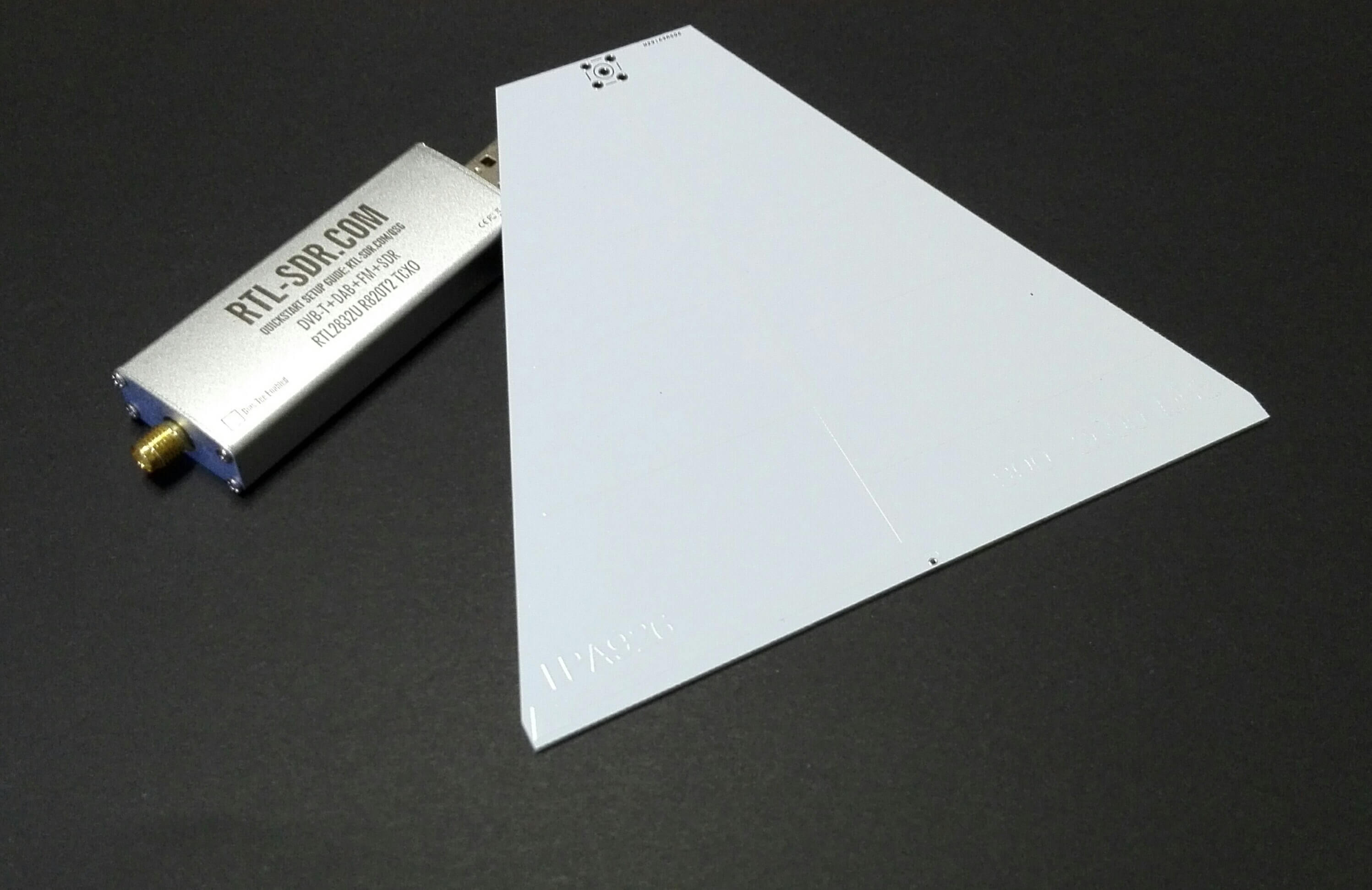
Ham radio enthusiast and RF designer Marco Cardelli (IZ5IOW) recently wrote in and wanted to share his PCB log periodic antenna design which he has been using together with RTL-SDR dongles. Log periodic’s are very wideband directional antennas that can easily be printed onto a circuit board.
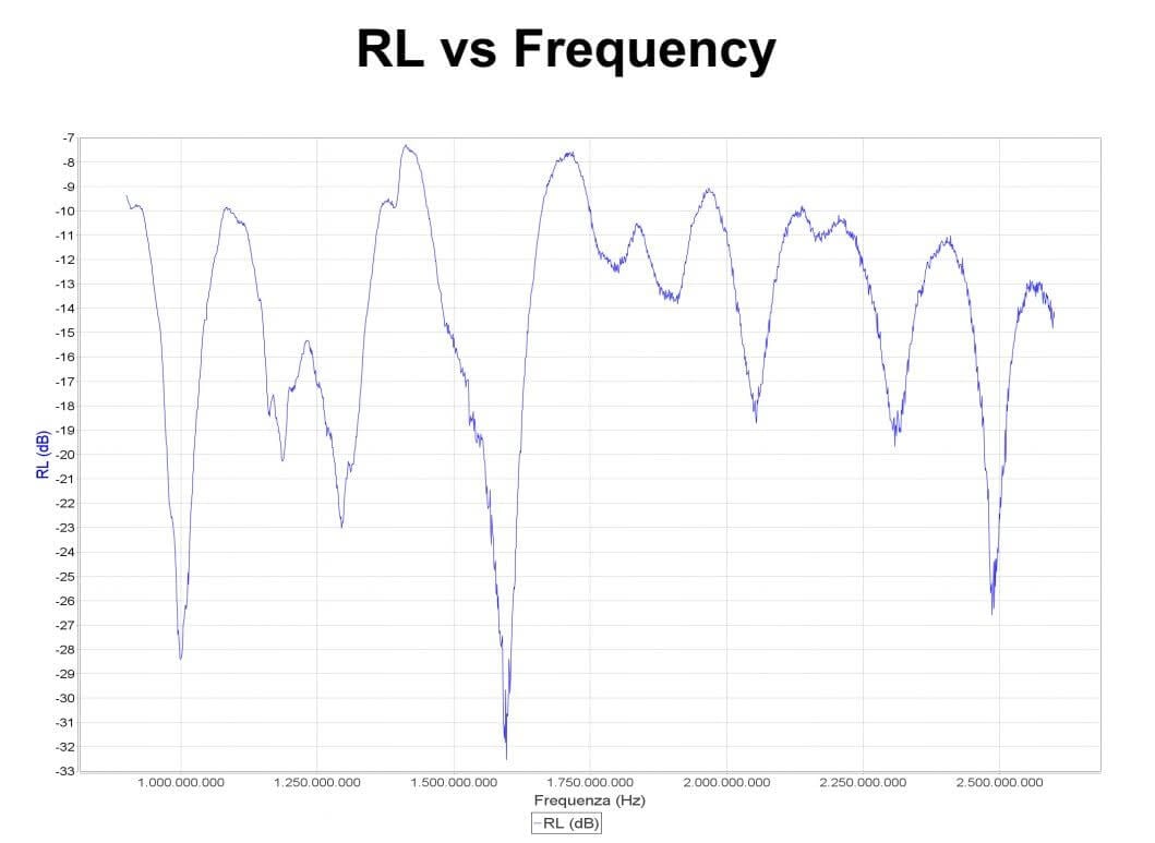
Marco’s antenna covers a frequency range of 900 MHz – 2600 MHz. The original principal focus was for EMI/EMC measurements, but Marco writes that it works perfectly fine for microwave experiments on the 23 and 13cm bands of wi-fi links. Marco currently uses this antenna for reception of microwave beacons. Currently there are no designs or plans on his website for the antenna, but we suspect that he will put them up soon.
If you’d rather purchase an antenna like this instead building one, then we’ve seen in the past good reviews from the PCB antennas available from wa5vjb at www.wa5vjb.com.
The wideband PCB log-periodic antenna.Return Loss of the PCB Log Periodic antenna.
Vivaldi’s are linearly polarized broadband antennas that have a directional radiation pattern at higher frequencies. The high end SDR manufacturer RF Space produces their own Vivaldi antennas made from PCB boards which they sell online. The larger the antenna, the lower its receiving frequency, and ones that go down to about 200 MHz are almost the size of a full adult person. But all sizes receive up to 6 GHz maximum. Typically smaller versions of Vivald antennas have been used in the past for L-Band satellite reception.
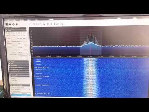
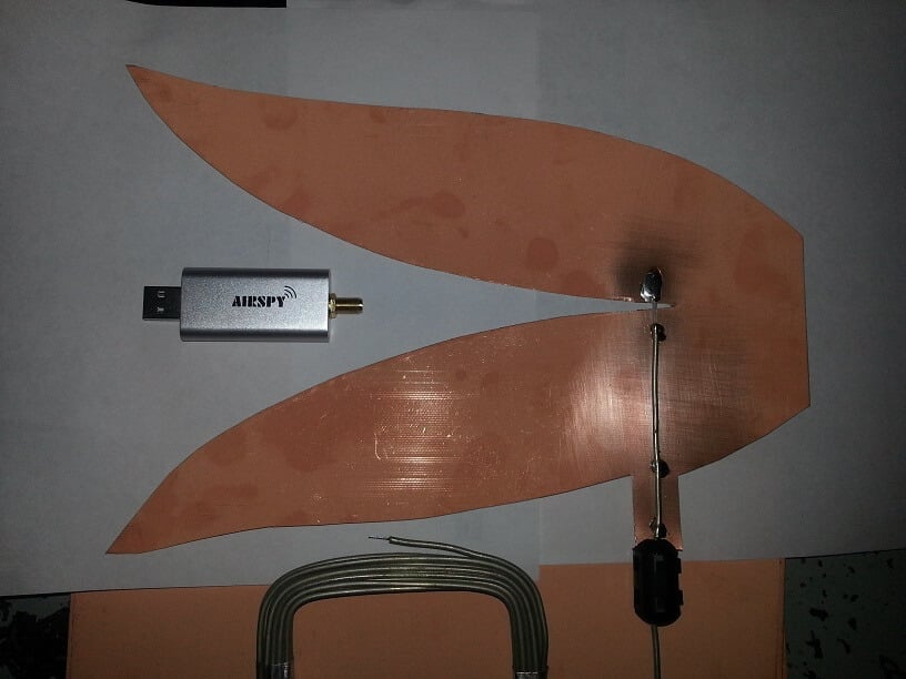
Over on his blog KD0CQ noted that he always had trouble trying to purchase a Vivaldi from RF Space because they were too popular and always out of stock. So he decided to try and build his own out of PCB boards. On this page he’s collected a bunch of Vivaldi cutout or transfer images. On his second page he shows a Vivaldi antenna that he built out of PCB material, just by using scissors and semi-rigid coax. With the Vivaldi placed outdoors he’s been able to successfully receive and decode L-Band AERO on his Airspy Mini even without an LNA.
KD0CQ writes that he’ll update his blog soon with more results.
Simple Vivaldi antenna by KD0CQ cut out of PCB board.