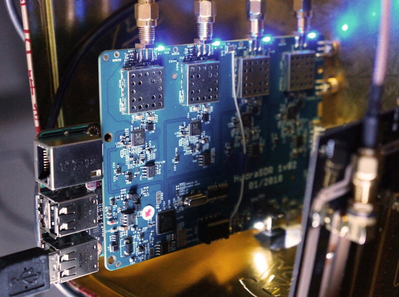
KerberosSDR (formerly HydraSDR) is our upcoming 4-input coherent RTL-SDR. It's designed for coherent applications like RF direction finding, passive radar, beam forming and more, but can also be used as a standard 4-channel SDR for monitoring multiple frequencies. In this post we demonstrate the direction finding application running on the TinkerBoard.
Reminder: If you have any interest in KerberosSDR, please sign up to our KerberosSDR mailing list. Subscribers to this list will be the first to know when KerberosSDR goes on preorder, and the first 100 sales will receive a discounted price.
KerberosSDR Updates
This week we've managed to get the KerberosSDR demo software made by Tamás Peto functioning on a TinkerBoard. The TinkerBoard is a US$60 single board computer. It's similar to a Raspberry Pi 3, but more powerful. We've also tested the app running on the Raspberry Pi 3 and Odroid XU4. The Pi 3 is capable of running the software but it is a little slow, and the Odroid XU4 is a little faster than the TinkerBoard. In the future we hope to further optimize the code so even Raspberry Pi 3's will be smooth.
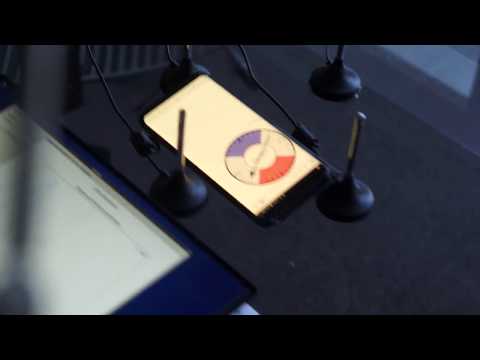
In the video below we used a circular array of four whip antennas connected to KerberosSDR. The TinkerBoard is connected to KerberosSDR and is set up to generate a WiFi hotspot, which we connect to with an Android phone and a Windows laptop. The Windows laptop connects to the TinkerBoard's desktop via VNC, and the Android phone receives an HTML/JavaScript based compass display via an Apache server running on the Tinkerboard. With this setup we can wirelessly control and view information from KerberosSDR and the TinkerBoard.
We've also tested the KerberosSDR system on a real signal, and have found it to work as expected. More demo's of that coming later.
Over the last few months we've been working on a 4-input coherent RTL-SDR called 'KerberosSDR' (formerly known as HydraSDR) that is designed to be a low cost way to get into applications such as RF direction finding, passive radar, beam forming and more. It can also be used as a standard 4-channel SDR for monitoring multiple frequencies as well.
Phase coherent RTL-SDRs have been worked on and demonstrated several times over the past few years, but we've been disappointed to find that so far there hasn't been any easy way to replicate these experiments. The required hardware has been difficult to build and access, and the software has been kept as unreleased closed source or has been too complicated to install and use. With KerberosSDR we aim to change that by making phase coherent applications easier to access and run by providing ready to use hardware and software.
Thanks to our developer Tamás Peto, a PhD student at Budapest University of Technology and Economics whom we hired via the ad in our previous post, and the Othernet (formerly Outernet) engineering team who are our partners on this project, we've been able to build a working system, and demonstrate coherent direction finding and passive radar working as expected (demo videos below). We plan to eventually release Tamás' code as open source so that the entire community can benefit and build on it. Also if KerberosSDR turns a profit, we plan to reinvest some of the profits into continually improving the software and expanding the list of use cases.
KerberosSDR will be usable for coherent applications from ~80-100 MHz up to 1.7 GHz (as a standard receiver it will work down to 24 MHz like a regular RTL-SDR). The lower coherent limitation is due to the phase calibration board, and could be improved by custom creating a larger calibration PCB.
At the moment we are finalizing our prototype, and plan to begin final production within the next 2-3 months.
If you have any interest in KerberosSDR, please sign up to our Kerberos mailing list.
Direction Finding
KerberosSDR can be used to find the bearing towards a signal using it's coherent direction finding capabilities. The software by Tamás currently implements several direction finding algorithms such as Bartlett, Capon, Maximum Entropy (MEM) and MUSIC. In the video below we show a quick test of the direction finding system working with a HackRF being used as a signal source, and four dipole antennas connected to KerberosSDR in a linear array. The MUSIC algorithm is used.
KerberosSDR Direction Finding Test
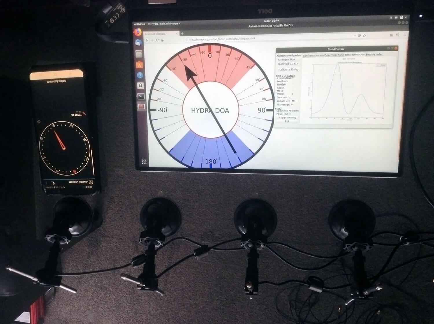
In the image below we also attempted to find the direction towards a known TETRA transmitter. We were able to confirm the direction with an Android compass app that points towards the known transmitter location. As the two angles match, we can be confident that Kerberos is finding the correct direction to the transmitter.
Finding the direction of a TETRA Transmitter
Passive Radar
KerberosSDR can also be used for passive radar. Normal radar systems work by transmitting a pulse of RF energy, and listening to the reflections from objects like planes, cars and ships. Passive radar works by using already existing transmitters such as those for FM/TV and listening for reflections that bounce of objects.
With a simple passive radar system you need two directional antennas and two coherent receivers. One antenna points at the transmitting 'reference' tower, and the other at the 'surveillance' area where you want to listen for reflections. It's important to try and keep as much of the reference signal out of the surveillance antenna as possible, which is why directional antennas like Yagi's are used.
The result is a doppler vs time delay graph, where the reflection of aircraft, cars, ships and other objects can be seen. The doppler gives you the speed of the object relative to your antenna and the transmitting tower, and the time delay gives you the distance relative to your antenna and the transmitter tower.
Below is an example time lapse video of KerberosSDR being used for passive radar. The reference antenna points towards a DVB-T transmitter at 588 MHz, and the surveillance antenna overlooks a small neighborhood, with aircraft sometimes flying over. The antennas we used were two very cheap TV Yagis.
You can constantly see the reflections from vehicles at small doppler values (low speeds), and every now and then you see an aircraft reflection which shows up at much higher doppler (speed) and further time delay (distance) points.
More information about KerberosSDR
KerberosSDR includes:
4x Coherent R820T2 based RTL-SDR dongles with standard 24 MHz - 1.7 GHz frequency range
On board GPIO switched wide band noise source for sample sync and phase calibration
Special phase calibration PCB for 4x inputs. Required to make the Kerberos phase coherent.
On board USB Hub, so only one USB port is required on the PC
Shielded metal enclosure
KerberosSDR can also be extended to 8x receivers by daisy chaining two boards together, so that their clocks and noise sources are connected. We've also taken into account undesirable effects such as heat related PLL drift which can be an issue for phase coherence.
At the moment we are also investigating whether singleboard computers like the Raspberry Pi 3 or Tinkerboard can be used, and there will be a header available for powering them via the Kerberos PCB. In the future we also plan to work on optimizing the code and potentially using CUDA/OpenCL GPU optimizations for passive radar so everything runs smoothly.
Once released we plan to have extensive tutorials and documentation that show exactly how to set up and replicate direction finding and passive radar experiments with low cost antennas.
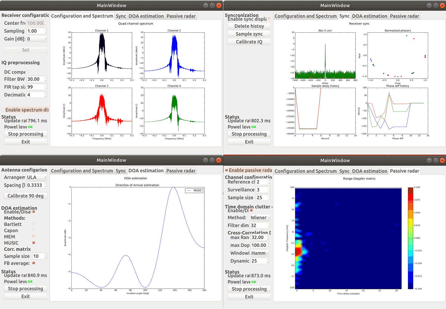
Screenshots of KerberosSDR software:
Screenshots of each KerberosSDR software screen
Remember, if you're interested please sign up to the KerberosSDR mailing list for announcements and the chance to get in early with the cheaper first 100 units.
Be on the look out for more interesting demos that will be posted in the coming weeks!
[the_ad id="14114"]
Update: Please note that due to a Trademark complaint, we have changed the name of this unit from HydraSDR to KerberosSDR.
KerberosSDR Updates: 27 August 18
This week we've managed to get the KerberosSDR demo software made by Tamás Peto functioning on a TinkerBoard. The TinkerBoard is a US$60 single board computer. It's similar to a Raspberry Pi 3, but more powerful. We've also tested the app running on the Raspberry Pi 3 and Odroid XU4. The Pi 3 is capable of running the software but it is a little slow, and the Odroid XU4 is a little faster than the TinkerBoard. In the future we hope to further optimize the code so even Raspberry Pi 3's will be smooth.
In the video below we used a circular array of four whip antennas connected to KerberosSDR. The TinkerBoard is connected to KerberosSDR and is set up to generate a WiFi hotspot, which we connect to with an Android phone and a Windows laptop. The Windows laptop connects to the TinkerBoard's desktop via VNC, and the Android phone receives an HTML/JavaScript based compass display via an Apache server running on the Tinkerboard. With this setup we can wirelessly control and view information from KerberosSDR and the TinkerBoard.
We've also tested the KerberosSDR system on a real signal, and have found it to work as expected. More demo's of that coming later.
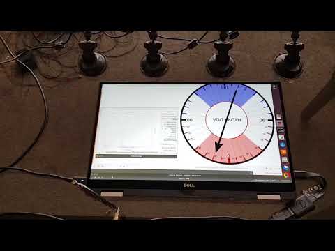
KerberosSDR Direction Finding Test 2: Tinkerboard + Circular Array
KerberosSDR Prototype with TinkerBoard Running Computations
KerberosSDR Updates: 4 September 2018
In this post we'll show an experiment that we performed which was to pinpoint the location of a transmitter using KerberosSDR's coherent direction finding capabilities. RF direction finding is the art of using equipment to determine the location of a transmitting signal. The simplest way is by using a directional antenna like a Yagi to try and determine the bearing based on signal strength. Another method is using a pseudo-doppler or coherent array of antennas to determine a bearing based on phase information.
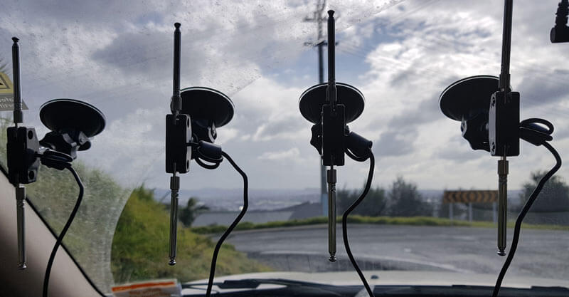
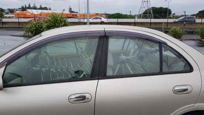
For the test we tuned the KerberosSDR RTL-SDRs to listen to a signal at 858 MHz and then drove to multiple locations to take direction readings. The antennas were set up as a linear array of four dipole antennas mounted on the windshield of a car. To save space, the dipoles were spaced at approximately a 1/3 the frequency wavelength, but we note that optimal spacing is at half a wavelength. The four dipole antennas were connected to KerberosSDR, with a laptop running the direction finding demo software.
Low cost direction finding array mounted to vehicle windshield.
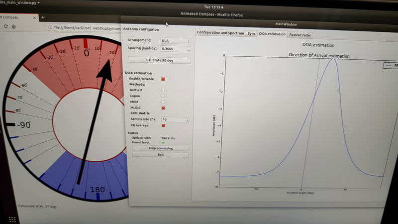
Our open source demo software (to be released later when KerberosSDR ships) developed by Tamás Peto gives us a graph and compass display that shows the measured bearing towards the transmitter location. The measured bearing is relative to the antenna array, so we simply convert it by taking the difference between the car's bearing (determined approximately via road direction and landmarks in Google Earth) and the measured bearing. This hopefully results in a line crossing near to the transmitter. Multiple readings taken at different locations will end up intersecting, and where the intersection occurs is near to where the transmitter should be.
KerberoSDR SDR Directing Finding DOA Reading
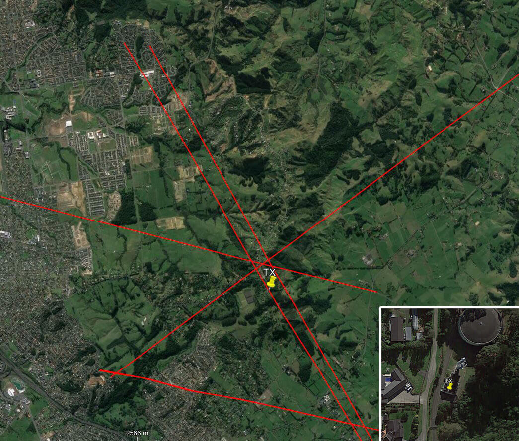
In the image below you can see the five bearing measurements that we made with KerberosSDR. Four lines converge to the vicinity of the transmitter, and one diverges. The divergent reading can be explained by multipath. In that location the direct path to the transmitter was blocked by a large house and trees, so it probably detected the signal as coming in from the direction of a reflection. But regardless with four good readings it was possible to pinpoint the transmitting tower to within 400 meters.
In the future we hope to be able to automate this process by using GPS and/or e-compass data to automatically draw bearings on a map as the car moves around. The readings could also be combined with signal strength heatmap data for improved accuracy.
This sort of capability could be useful for finding the transmit location of a mystery signal, locating a lost beacon, locating pirate or interfering transmitters, determining a source of noise and more.
KerberosSDR pinpointing a transmitters location
KerberosSDR Updates 7 September 2018
For this test we parked our car to the side of a highway and pointed a cheap DVB-T Yagi antenna towards a DVB-T transmission tower, and another cheap Yagi down the road. The video shown below displays the results captured over a 5 minute period. The blips on the top half of the display indicate vehicles closing on our location (positive doppler shift), and the blips on the bottom half indicate objects moving away (negative doppler shift).
DVB-T Antennas In Car
The resolution of each individual vehicle is not great, but it is sufficient to see the overall speed of the highway and could be used to determine if a road is experiencing traffic slowdowns or not. When larger vehicles pass by it is also obvious on the display by the brighter blip that they show. The display also shows us that the highway direction coming towards us is much busier than the direction moving away.
In the future we'll be working on optimizing the code so that the display updates much faster and smoother. It may also be possible in the future to use the third and fourth tuners to obtain even greater object resolution.
KerberosSDR Updates 27 September 2018
In this post we're showing some more passive radar demos. The first video is a time lapse of aircraft coming in to land at a nearby airport. The setup consists of two DVB-T Yagi antennas, with KerberosSDR tuned to a DVB-T signal at 584 MHz. The reference antenna points towards a TV tower to the west, and the surveillance antenna points south. Two highlighted lines indicate roughly where reflections can be seen from within the beam width (not taking into account blockages from mountains, trees etc).
The second video shows a short time lapse of a circling helicopter captured by the passive radar. The helicopter did not show up on ADS-B. On the left are reflections from cars and in the middle you can see the helicopter's reflection moving around.
We are expecting to receive the final prototype of KerberosSDR within the next few weeks. If all is well we may begin taking pre-orders shortly after confirming the prototype.
Earlier this month we posted about the KiwiSDR direction finding update, which now allows anyone with internet access to utilize public KiwiSDR's for the purpose of pinpointing the physical location of a transmitter that transmits at a frequency below 30 MHz.
A few people have had trouble understanding how to use the direction finding feature, so KiwiSDR fan Nils Schiffhauer (DK8OK) has written up a KiwiSDR direction finding usage guide. Nils' guide explains the basic technical ideas behind the TDoA (Time Difference of Arrival) direction finding technique used, and highlights some important considerations to take into account in order to get the best results. For example he discusses best practices on how to choose receiver locations, how many receivers to choose, and how to properly take into account the time delaying effects of ionospheric propagation with HF signals.
Finally at the end of the document he shows multiple case studies on HF signals that he's managed to locate using the discussed best practices. Looking through these examples should help make it clear on how receiver locations should be chosen.
A few weeks ago we posted about some experimental work going on with Time Difference of Arrival (TDoA) direction finding techniques on KiwiSDR units. The idea is that public KiwiSDRs distributed around the world can be used to pinpoint the physical locations of any 0 - 30 MHz transmitter using the TDoA technique. This feature has recently been activated and can be accessed for free via any KiwiSDR.
The KiwiSDR is a US$299 HF SDR that can monitor the entire 0 - 30 MHz band at once. It is designed to be web-based and shared, meaning that the KiwiSDR owner, or anyone that they've given access, can tune and listen to it via a web browser over the internet. Many public KiwiSDRs can be found and browsed from the list at sdr.hu or by signal strength and location on this website.
One thing that KiwiSDRs have is a GPS input which allows the KiwiSDR to run from an accurate clock, as well as providing positional data. Time Difference of Arrival (TDoA) is a direction finding technique that relies on measuring the difference in time that a signal is received at over multiple receivers spread out over some distance. In order to do this an accurate clock that is synchronized with each receiver is required. GPS provides this and is able to accurately sync KiwiSDR clocks worldwide.
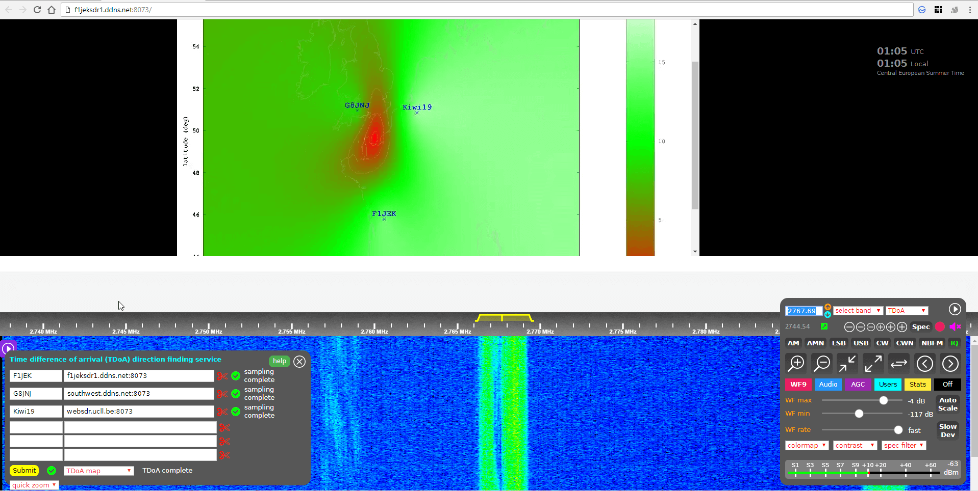
Just recently all KiwiSDRs were pushed with a beta update (changelog) that enables easy TDoA direction finding to be performed with them. Since many KiwiSDRs are public, this means that right now anyone can browse to a KiwiSDR web interface and start a direction finding computation. You don't even need to own a KiwiSDR to do this so this is the first freely accessible RF direction finding system available to the public. This could be useful for locating signals like numbers stations, military transmissions, pirate stations, jammers and unknown sources of noise.
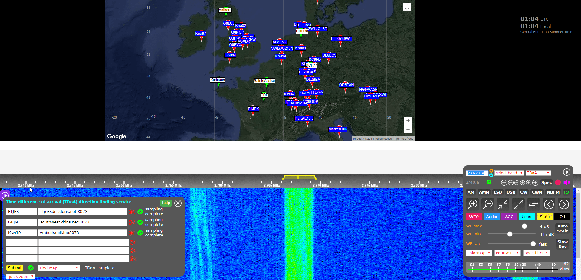
KiwiSDR TDoA Interface. Locating a STANAG Signal Source.
Usage
Running a TDoA job is as simple as using the KiwiSDR OpenWebRX GUI interface to select a signal and choose two or more receivers to use in the calculation.
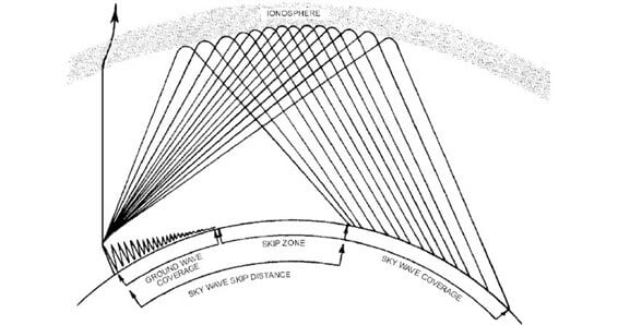
If you want to try this out then it's easiest to start with VLF/LF or MW stations (less than 1.6 MHz) as these signals tend to propagate to receivers only via direct ground wave. HF sky wave signals are a bit more difficult to locate as they tend to travel longer distances by skipping, bouncing and refracting around the ionosphere, so it is difficult to determine exactly where they are coming from since the bounces result in a difficult to predict time delay. But if you know the rough location of the transmitter, you can try and select nearby KiwiSDR receivers, which will hopefully ensure that the signals are received directly via ground wave, and not via sky wave. More advanced users could try using receivers spaced further away, but at similar distances from the expected transmitter location. This will hopefully ensure that all the receivers have identical skip distances, and thus identical delays.
Sky wave and ground wave propagation. Ground wave is received directly vs sky wave which is received via ionospheric bounces
To get started follow these steps (and we also recommend reading the Help text, which is available by clicking the 'Help' button on the TDoA extension):
Open a KiwiSDR that can receive some signals that you are interested in locating. You can browse KiwiSDRs by map and signal strength quality on this website.
With the 'extension' drop down menu in the bottom right controls window choose TDoA and double check that the receiver modulation mode is set to 'IQ'.
You should now see a map on the top half of the screen. This map displays all KiwiSDRs in the world that have GPS enabled and thus can be used for TDoA.
The map also displays several known transmitters in white with green markers that can be used as TDoA practice. Clicking on a known transmitter will automatically tune the KiwiSDR to that station.
Tune to the signal that you are interesting in locating. Make sure that the receiver bandwidth covers the signal.
Now you need to find two or more KiwiSDRs on the map that can receive the signal that you're interested in locating. (Two will give you a line of possible locations, whilst three may allow you to pinpoint the signal. But we recommend starting with only two or three first as more receivers can cause the calculation to fail).
To test and see if a KiwiSDRs from the map can receive the signal, double click on its marker. This will open the selected KiwiSDR in a new browser window, with it tuned to the station of interest. If you have a rough idea on where the transmitter is located, try to select KiwiSDRs such that they surround the transmitter.
Once you've found a KiwiSDR that receives your signal of interest, close the second KiwiSDR receiver window that you just opened, and go back to the original KiwiSDR window. Now instead of double clicking just click once on the KiwiSDR pin on the map that you confirmed reception with. This will add that KiwiSDR to the window in the bottom left. This window displays the KiwiSDRs that will be used in the TDoA calculation.
Make sure that it shows "XX GPS fixes/min" beside a selected KiwiSDR. If you get an error, remove that KiwiSDR and choose another.
When you've found two or more KiwiSDRs that receive the signal of interest, position the map to where you'd like the TDoA result heat map to be displayed. The positioning of the KiwiSDR map will determine where the TDoA heat map plot is displayed.
Click the 'submit' button to begin the TDoA calculations. The KiwiSDR server will gather 30 seconds of samples from each of your selected KiwiSDRs, and then run the TDoA algorithm on the KiwiSDR server. The whole process should take about 1-3 minutes to complete.
Once completed you can view the results by using the drop down menu next to the submit button to choose the 'TDoA Map'
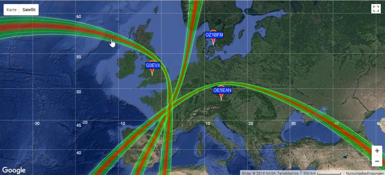
KiwiSDR TDoA Heat Map Results. Located a Military STANAG Signal Source in France.
The KiwiSDR TDoA feature is still in testing and can be a little buggy. If you get "Octave Error", try refreshing the KiwiSDR page and trying again with different receivers. Sometimes you'll also get an error saying that the GPS of a KiwiSDR hasn't updated in a while. In this case just remove that receiver and choose another one. We also find that if you're zoomed too far out on the map, the TDoA algorithm will sometimes return 'Octave error'. Try zooming in a bit closer to the approximately expected location. KiwiSDRs can also only support four simultaneous users at a time, so during peak periods it's possible that some may become busy.
Over on the KiwiSDR forums Martin G8JNJ has also provided a list of helpful tips that he's discovered. For example he recommends choosing KiwiSDRs that are spaced evenly around the estimated transmitter location (if known). Ideally they should also be chosen an opposing pairs (e.g. one pair north and south of the transmitter, and one east and west of it).
Results
We tested the new TDoA feature a few times. Below are some examples of the results we achieved.
USA: NLK @ 24.6 kHz.
This is a Naval transmitter located in Seattle, Washington. With three receivers surrounding the transmitter, we were able to get a pretty close location marker, that is confirmed with the known location.
USA NLK
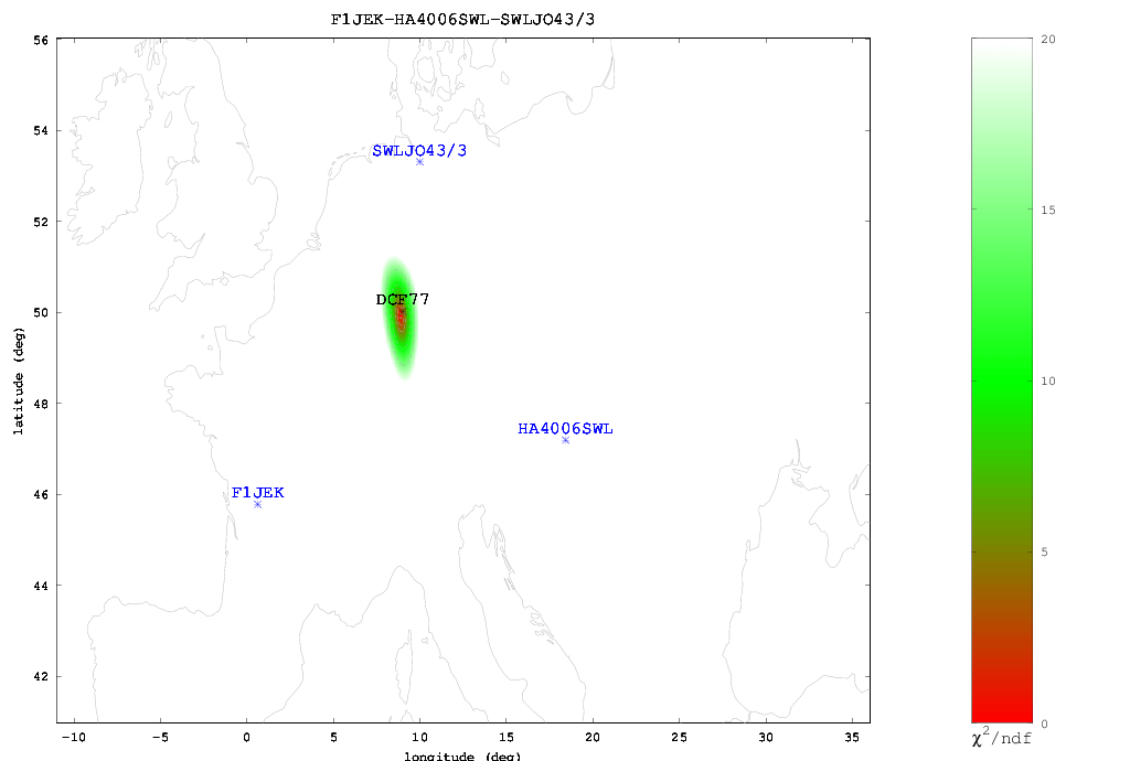
Europe: DCF77 Time Beacon @ 77.5 kHz.
This is a German long wave time beacon transmitter. Again with three receivers we were able to pinpoint the signal fairly accurately.
DCF77 Located with KiwiSDR TDoA
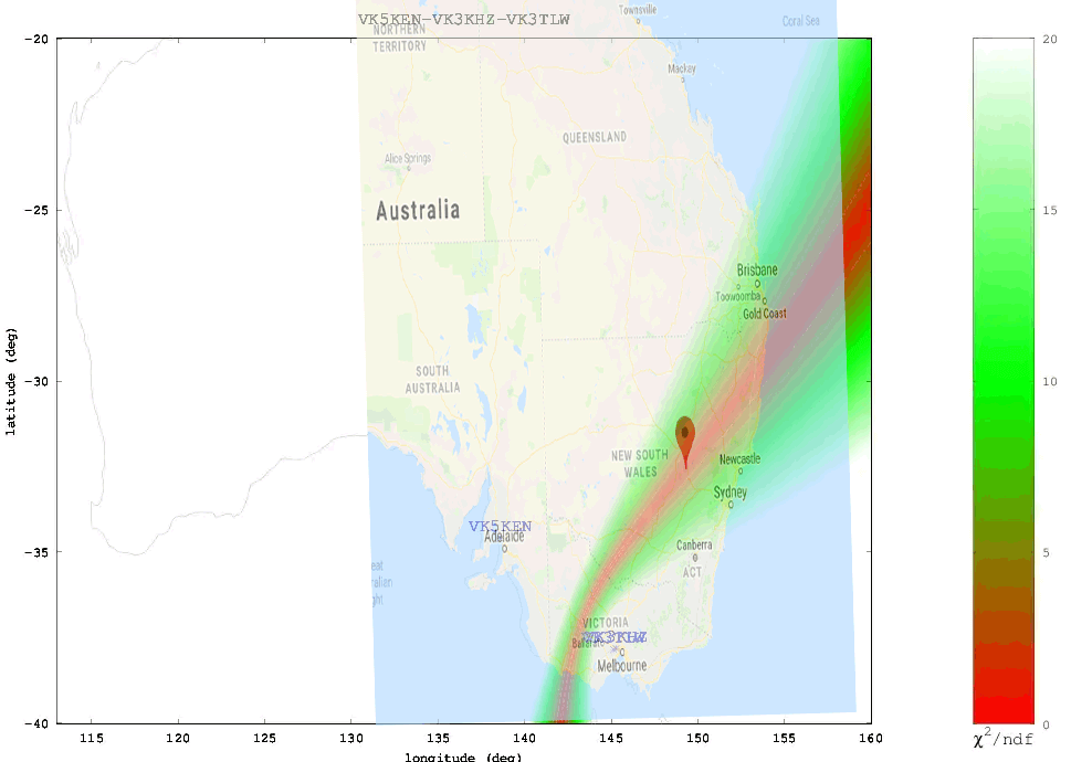
Australia: Local MW Radio Station @ 549 kHz.
Here we tried to locate an Australian MW station. Unfortunately in Australia there is a lack of KiwiSDRs, and of the ones that are there, only three had GPS enabled and could receive the MW station, and two of those were right next to each other. With only effectively two stations we could only obtain a line of possible locations. Comparing with the known location plotted on Google Maps we confirmed that the transmitter is indeed located on the line.
ABC Western Plains Australian MW Radio Station
We also tested a few signals at higher frequencies. As mentioned previously, anything above VLF/LF/MW (ie the HF bands) is a lot more difficult to locate since the signal can bounce around the atmosphere and can case extra delays to occur in the signal arrival time. The extra delays can cause problems with the time of arrival measurements. Thus for these signals it's important to find receivers close to the transmitter, or receivers spaced further away at the same distance so they each have identical skip distances, and thus identical delays.
When locating an HF signal that is in a completely unknown location we recommend starting with only two or three receivers, checking the heat map, and slowly adding more receivers in the hot parts of the heat map and removing receivers that turn out to be in the cooler areas. This way you can slowly narrow down the receivers to ones that are closer to the signal source, and are thus more likely to receive the signal directly, rather than via ionosphere bounces.
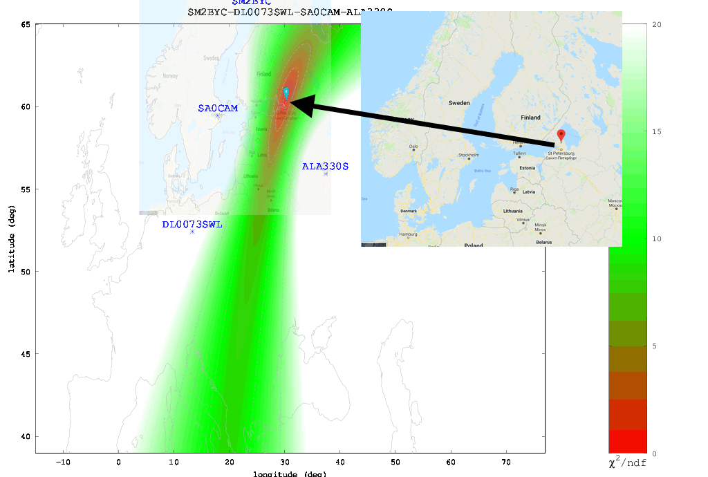
The Buzzer (UVB-76)
Using the just previously mentioned technique we attempted to locate the source of the Buzzer (UVB-76), a Russian numbers station at 4.625 MHz. Eventually we came to the results shown below. According to the heat map the buzzer appears to be located somewhere in the vicinity of St. Petersburg. Back in 2014 the numbers station researchers at priyom.org received an anonymous tip from a member citing a transmitter location just north of St. Petersburg. The TDoA heat map results seem to confirm that the anonymous tipper is correct.
The Buzzer (UVB-76) TDoA Heatmap compared against the known location
Final Words
Right now the biggest problem appears to be the lack of active KiwiSDRs around the world. The more active KiwiSDRs there are, the better the direction finding results can be. At the moment Northern Europe and the USA are fairly well represented, but the rest of the world is not. Asia, Africa, Russia and South America are especially lacking. Also not all KiwiSDRs are utilizing the GPS feature. If you are running a KiwiSDR please do consider activating the GPS option. Another issue is that many KiwiSDRs suffer from poor reception and bad antenna setups, so not all active receivers are actually useful.
In the future we expect this feature to only improve, with the people behind it, John Seamons and Christoph Mayer, working hard to improve results. For example one possible future improvement is utilizing ray-tracing techniques to try and take into account delays caused by sky-bounce propagation. Update (15 July 2018): You can now also plot results over Google Maps.
If you want to purchase a KiwiSDR and contribute to the worlds first freely accessible TDoA system, you can purchase it immediately on Amazon or Seeed Studios for $299, or wait for a sale to occur on massdrop.com, where it is often discounted by up to US$100.
If you weren't already aware, the KiwiSDR is a US$299 HF SDR that can monitor the entire 0 - 30 MHz band at once. It is designed to be web-based and shared, meaning that the KiwiSDR owner, or anyone that they've given access, can tune and listen to it via a web browser over the internet. Many public KiwiSDRs can be found and browsed from the list at sdr.hu.
One thing that KiwiSDRs have is a GPS input which allows the KiwiSDR to run from an accurate clock, as well as providing positional data. Time Difference of Arrival (TDoA) is a direction finding technique that relies on measuring the difference in time that a signal is received at over multiple receivers spread out over some distance. In order to do this an accurate clock that is synchronized with each receiver is required. GPS provides this and is able to accurately sync KiwiSDR clocks worldwide.
In one post from late last year Christoph shows that he was able to pinpoint the location of the German DCF77 longwave time station by using three KiwiSDRs spread out around Europe. The actual location of DCF77 is already known, so this shows that the technique actually works. Other posts show him locating transmitters for STANAG 4285, some unknown frequency hopping signals, OTH radar from Cyprus, CODAR, DRM, VOLMET and more.
Christophs' code can be found at https://github.com/hcab14/TDoA. According to users gathering the data and running the code is still a fairly elaborate process. But there is talk over on the KiwiSDR forums about eventually creating a server that would allow users to more easily request a location computation for a particular signal.
Pinpointing DCF77 with KiwiSDRs (Bottom right image shows pinpointed location)
Also related to this topic, priyom.org has been using KiwiSDRs to try and locate numbers stations. Numbers stations are mysterious voice stations on the HF bands that when transmitting read out a string of numbers. Most speculate that the numbers are some sort of code intended for international spy agents. Using a simpler method of just noting which KiwiSDRs in the world receive a particular numbers station more strongly, they've been able to determine the likely country of some well known stations.
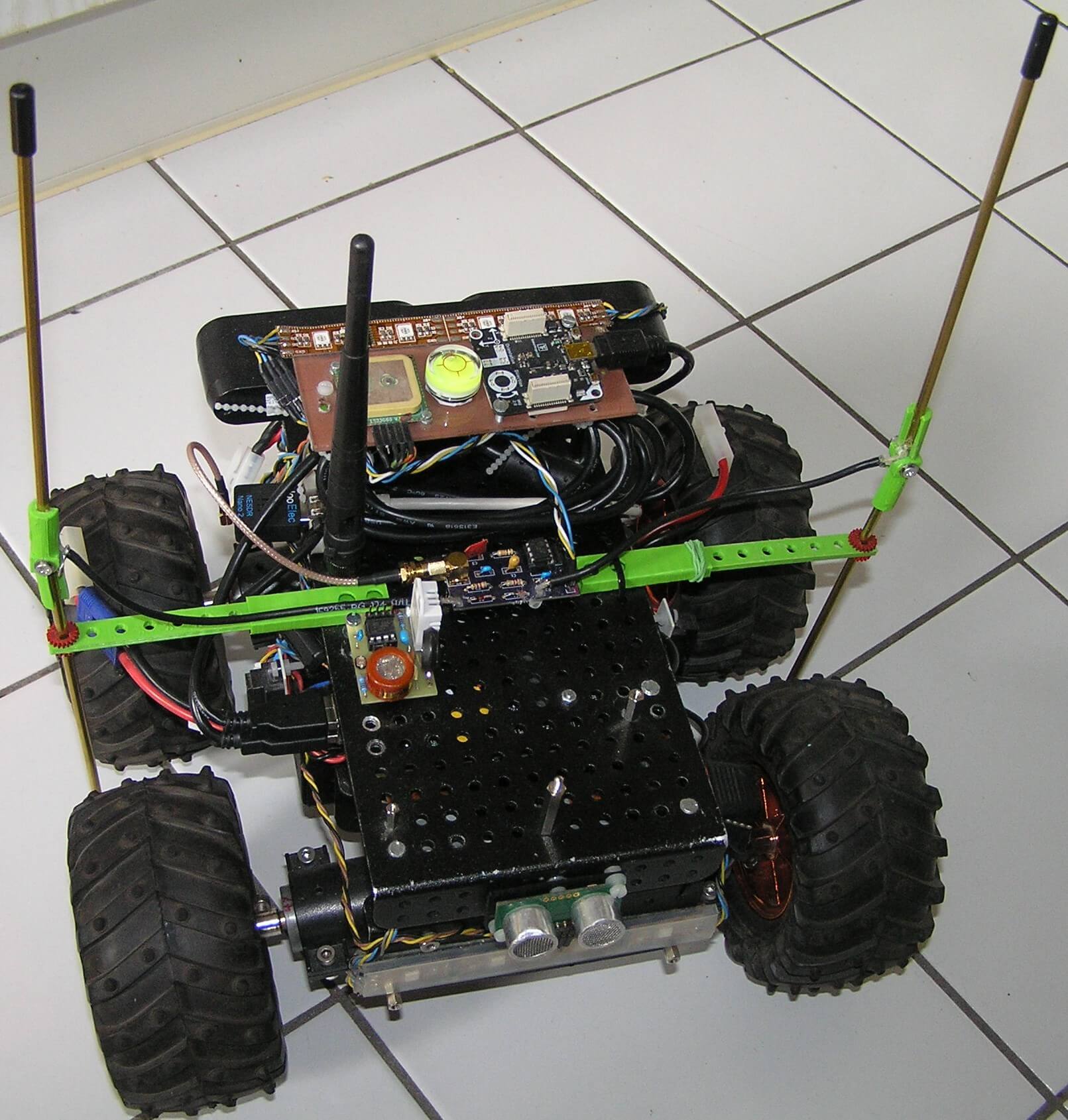
Over on Hackaday.io, project logger Humpelstilzchen has been writing about his attempts to create an autonomous RF direction finding robot RC car with an RTL-SDR. The goal is to set up an ISM band transmitter as a beacon, and use the RTL-SDR on the robot as the receiver. It will then use direction finding techniques to drive towards the beacon. The robot is a 4WD RC toy car with some autonomous navigational features like GPS, ultrasonic, IMU and vision sensors.
In his latest project log Humpelstilzchen describes his first semi-successful attempt at getting RF direction finding working. In the experiment he uses a 433 MHz module to send out an FSK beacon. On the robot two antennas are used for the time difference of arrival/pseudo-doppler direction finding technique, and PIN diodes are used to rapidly switch between the antennas. A GNU Radio script running on a HummingBoard single board computer computes the TDOA/pseudo-doppler algorithm.
Psuedo-doppler direction finding works by rapidly switching between several antennas. The difference in the time that the signal arrives at each antenna can be used to calculate the transmitter's direction.
With the current set up he's been able to get the robot to distinguish if the beacon is closer to the left, or closer to the right, or equidistant. However, he notes that there are still problems with reflections of the beacon signal which can cause the robot to drive in the wrong direction.
This is still a work in progress and we look forward to his future results.
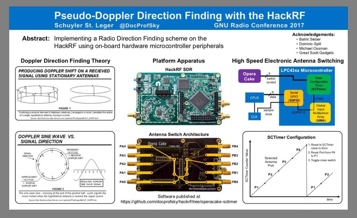
Last week we posted about Micheal Ossmann and Schuyler St. Leger's talk on Pseudo-Doppler direction finding with the HackRF. The talk was streamed live from Schmoocon 18, but there doesn't seem to be an recorded version of the talk available as of yet. However, Hackaday have written up a decent summary of their talk.
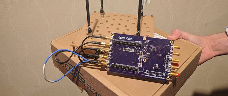
In their direction finding experiments they use the 'Opera Cake' add-on board for the HackRF, which is essentially an antenna switcher board. It allows you to connect multiple antennas to it, and choose which antenna you want to listen to. By connecting several of the same type of antennas to the Opera Cake and spacing them out in a square, pseudo-doppler measurements can be taken by quickly switching between each antenna. During the presentation they were able to demonstrate their setup by finding the direction of the microphone used in the talk.
If/when the talk is released for viewing we will be sure to post it on the blog for those who are interested.
OperaCake running with four antennasSchyler's Poster on Pseudo Doppler from GNU Radio Con 17.
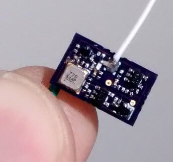
Over on Hackaday.io we've come across a project by "Tom" who has created a small tracking device which is located using an RTL-SDR dongle and directional Yagi antenna. The tracking device itself is a simple fingernail sized low power UHF transmitter that transmits short pulses about every second or so in the 915 MHz ISM band. Tom writes that the range is about 400m (line of sight) and with a small button cell battery the device lasts a couple of days with its 180 uA current draw. Presumably longer operation could be achieved by significantly reducing the pulse rate of the circuit.
To receive the tracking device an RTL-SDR is combined with a high gain directional Yagi antenna, a three level 10 - 30 dB attenuator and an Android phone running the RF Analyzer app. The idea is to simply use the attenuator and directional Yagi antenna to determine the direction in which the signal is strongest. That direction with the strongest signal will indicate where the transmitter is. Tom's video below shows an example of the transmitter and RTL-SDR based tracking setup.