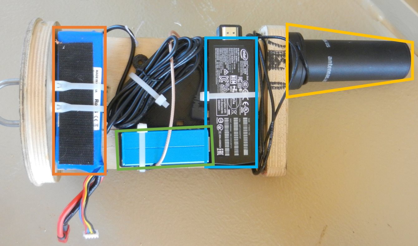
Over on the SDRGPS blog Philip Hahn and fellow aerospace engineer Paul Breed have been working together to try and use an RTL-SDR to help get accurate GPS data for tracking small high powered rockets. They write that their end goal is to be able to “track high power rockets in high acceleration / speed / altitude environments”.
In their latest attempt they launched a rocket with an RTL-SDR on board with it capturing GPS data to be later processed with GNSS-SDR. The goal was to get a GPS fix throughout the flight. Unfortunately they found that a good fix was only obtained while the rocket was on the ground, and not much data was obtained while it was in the air. They write that they suspect that the fault lies in the vibration in the rocket which can affect the frequency stability of the crystal oscillator, or in the GPS satellite tracking loop algorithm.
They still hope to be able to get some usable information from the flight by trying other algorithms on the data, but they are also seeking advice from anyone who might know how to help them, so please contact them if you know anything that may help.
According to various reports the Russian Meteor M-N2 satellite appears to be active again once more. The Meteor M N-2 is a polar orbiting Russian weather satellite that was launched in July 2014. It transmits with the LRPT protocol which allows us to receive weather satellite images with an RTL-SDR that are of a much higher resolution than the NOAA APT satellites.
Unfortunately late last year Meteor M N-2 had some problems and LRPT transmissions were turned off for the time being. During this downtime the Russian space agency switched the LRPT transmitter on the older Meteor M N-1 satellite back on, even though the satellite was tumbling in orbit. Currently people are not reporting any signal from Meteor M N-1, so this may have been turned off, perhaps temporarily.
Now however, it seems that Meteor M N-2 has been switched back on again and various people have already successfully received its signal. If you want to receive these Meteor M N-2 weather images with an RTL-SDR dongle or other SDR then you can view the tutorial written by Happysat here.
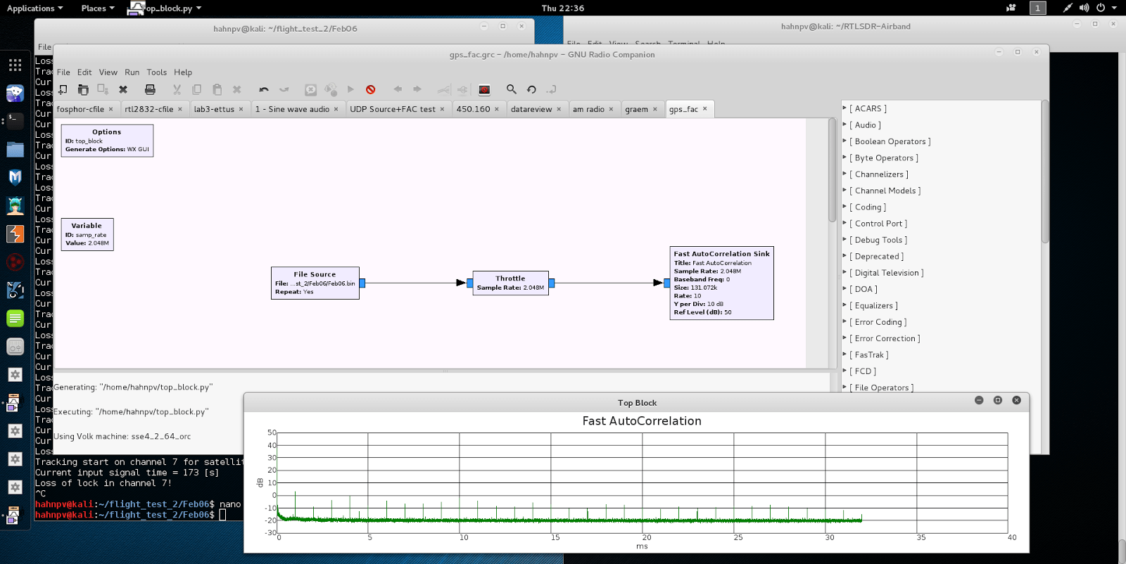
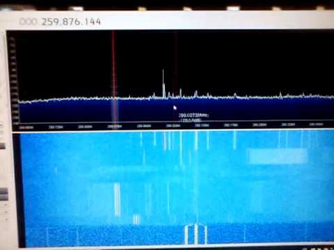
If you were to try to simply spot a GPS signal at 1.575 GHz in the spectrum on a waterfall in a program like SDR# you would probably fail to see anything. This is because GPS signals are very weak, and operate below the thermal noise floor. Only through clever processing algorithms can the actual signal be recovered.
With real data passed through the fast autocorrelation block he is able to observe GPS signal peaks that occur every millisecond. E.p. explains the reason for this:
Why every millisecond? The coarse/acquisition code for GPS (C/A) has a period of 1023 chips which are transmitted at a rate of 1.023 MBit/s. This results in period of 1 millisecond. BAM!
Last week we posted how programmer Jonti had successfully implemented a C-Band AERO decoder into his JAERO software. C-band AERO signals are the earth downlink portion of AERO. Planes transmit data upwards towards the satellites and then the Inmarsat C-band transmitter re-transmits the information back to a basestation on earth. This is different to the L-band AERO signals which are signals transmitted from the satellites to the aircraft. C-band signals are interesting because they contain plane position info, and so can be used to track aircraft much like what is done with ADS-B reception, but over a much larger area. However, C-Band signals are much more difficult to receive as they are at 3.616 GHz and require a 1.8m or larger satellite dish.
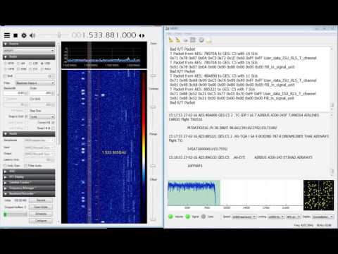
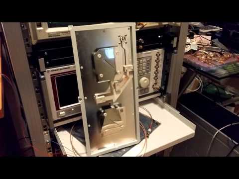
Over on YouTube user AceBlaggard has uploaded a video showing an example of C-Band signals being received with an Airspy SDR and being decoded with the new version of JAERO. About the hardware used AceBlaggard writes:
Hardware is a 1.8M PF dish and Titanium Satellite C1 PLL LNB feeding a Prof-Tuner 7301 sat card which loops out to an Airspy SDR.
Over on YouTube Adam Alicajic 9A4QV (creator of the popular LNA4ALL) has uploaded a video showing a comparison of reception of Thuraya satellites with a LHCP (left hand circular polarization) and RHCP (right hand circular polarization) patch antennas. To receive Thuraya satellites, a LHCP antenna should be used, and Adam’s results show that using an antenna with the wrong polarization (RHCP) produces a signal that is as theoretically expected almost 20dB lower. Shortly after initially posting this Adam wrote in to comment on the following:
Thuraya LHCP original patch antenna have 2 patches stacked inside the panel antenna and the hand made RHCP patch antenna is made only of 1 patch. Theoretically, this should give the 3dB more gain for the Thuraya antenna.
The difference in the received signal due to polarization should be (theoretically) 20dB, thats RHCP vs. LHCP and I experience some 18dB of difference which is good result. Why not 20dB? First of all it is impossible to get 3dB more gain stacking the antennas, this is just the theory, more likely 2db in the practice.
To receive the signals Adam uses the patch antennas, which are connected to the MIX4ALL (a downconverter that he is currently developing), which is then connected to a RTL-SDR dongle.
In the first video Adam shows the difference the wrong polarization makes, and in the second he shows some information about the Thuraya LCHP antenna he uses.
Receiving Thuraya sat - LHCP and RHCP comparison using MIX4ALL
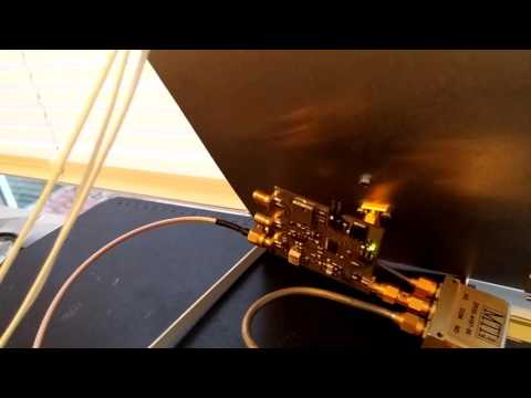
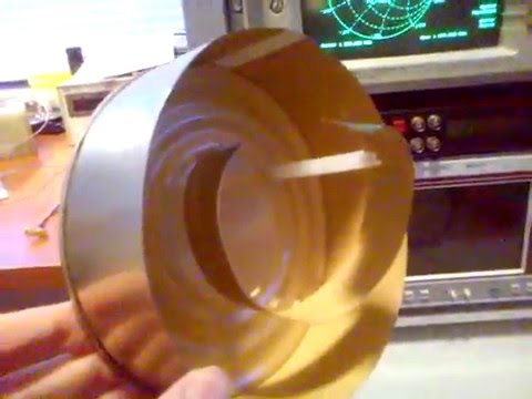
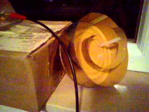
Over on YouTube user Adam Alicajic (creator of the popular LNA4ALL low noise amplifier) has uploaded a video showing the performance of a home made wideband helix antenna that he has created for receiving signals such as ones from L-Band Inmarsat satellites. See our tutorial for more information on receiving Inmarsat signals.
Adams helix antenna is built out of an old used can and is based on a 1.1 turn design. In the first of three videos he shows that the SWR of the antenna is all well below 2.0 from 1.5 GHz to 3 GHz. In the second video Adam shows the performance of the helix antenna on actual L-band signals being received with an RTL-SDR dongle. In the final video Adam compares the helix again a patch antenna and finds that the two receive with very similar performance.
The Meteor M N-2 is a polar orbiting Russian weather satellite that was launched in July 2014. It transmits with the LRPT protocol which allows us to receive weather satellite images that are of a much higher resolution than the NOAA APT satellites. For a while since the launch RTL-SDR users had a good time receiving beautiful images from Meteor M-N2, but unfortunately since late last year the N2 LRPT transmitter has been turned off, due to technical problems with the IR sensors as cited by Russian meteorologists.
Fortunately for Meteor N2 enthusiasts the old Meteor M N1 satellite which was thought to be dead sprung back into life around November 2015. Recently Matthew A., a reader of our blog wrote in to let us know that while N2 is still not transmitting, N1 is still transmitting, albeit with somewhat distorted images. Matthew also mentions this link: http://homepage.ntlworld.com/phqfh1/status.htm, which contains up to date info on the status of all weather satellites. He also writes:
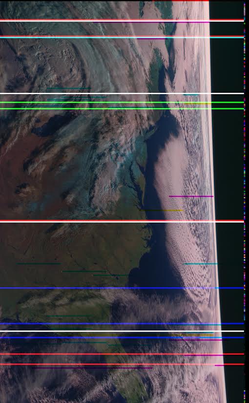
While transmissions are readily detectable and decodable at night, it seems that M N-1’s infrared sensors are not functioning. Yielding only black, with the typical noise bars of Red, Green, or Blue
As has been previously mentioned, Meteor MN-1’s stabilization system has obviously failed, and the horizon is clearly visible. Perhaps not of scientific value, but certainly beautiful.
We also note that there are several comments over on the Meteor-M N2 news and support website regarding receiving images from N1 and N2. It seems that sometimes N1 also has some problems with transmission, but they are usually quickly fixed.
The two most important things to pay attention to when receiving AERO signals are signal SNR and frequency stability. In order to lock on to the signal, the signal’s frequency must remain relatively stable over a short period of time. For the stability test Jonti writes the following, referencing the image posted below:
You can see the old RTL dongle moves almost 3kHz within a couple minutes after being turned on, this speed is so rapid that JAERO can’t keep up with the frequency changed during this period of time. What’s odd is the old RTL dongle does some fairly crazy stuff around 20 minutes in that lasts for about 15 minutes, JAERO also can’t cope with some of that. The other thing to notice in the old RTL’s spectrograph are vertical lines, these lines I believe are caused by interference entering the dongle between the RTL dongle’s tuner and ADC (analog-to-digital converter).
The frequency stability of the new RTL dongle can only be described as amazing!!! There is not much more than 100 Hz change during the whole test.
The range of frequencies for the SDRPlay is similar to that of the old RTL dongle of about 3kHz. The difference being the transition from the lowest frequency to the highest frequency is slow. Any demodulator should not have any issue tracking this slow and steady change. The only problem you will encounter here is when you are trying to tune into a particular frequency your frequencies will be slightly different depending on the temperature of the SDRPlay.
The results of the frequency stability test on an AERO signal. Left: Standard RTL-SDR; Middle: RTL-SDR Blog Unit; Right: SDRplay.
Jonti also found that in terms of sensitivity the SDRplay was the best at receiving when a non active antenna (an active antenna is an antenna with a built in LNA) was used. The RTL-SDR dongles could not receive well at all when a non active antenna was used. When an active GPS antenna was used the SDRplay was only about 1dB more sensitive than the RTL-SDR dongles.
In his article Jonti expressed concern that the SDRplay did not see much improvement in SNR over the RTL-SDRs when an active antenna was used. Our thoughts on the sensitivity findings are that the SDRplay does not see much improvement with an active antenna because the noise figure of the system is not reduced any further by adding an additional front end LNA (the noise figure in a RF system is almost entirely determined by the first LNA in a RF chain). Adding an extra LNA could even potentially make reception worse by reducing the overall linearity of the system. An external LNA would only be beneficial if a long run of coax was used between the feed and SDR, and in Jonti’s connections he connected the feed and SDRplay with a very short cable. The RTL-SDR only works well with an active antenna because its raw sensitivity at 1.5 GHz isn’t great, and it needs the extra boost from the LNA.