Using a TV Antenna Tap as a Directional Coupler for Antenna Measurements with an RTL-SDR
Over on his blog Tomi Engdahl has been exploring his options for measuring the VSWR of antennas with an RTL-SDR. As discussed in one of our previous tutorials, by using an RTL-SDR, noise source and directional coupler it is possible to roughly estimate the resonant frequency of an antenna.
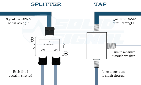
However, being without a directional coupler Tomi looked for other options and realized that cheap TV antenna network taps are also directional couplers. Taps are commonly used with Cable and Satellite TV installations to split a signal from an antenna over multiple TVs. They are designed as directional couplers to ensure that unwanted signals do not feed back into the antenna system and so that there is a pass through port to continue the strong signal down a long cable.
Note that there is a difference between a tap and a splitter. Taps are used when multiple devices need a signal over a long run of cabling. A splitter divides the signal strength by the number of out ports and can feedback unwanted signals into the system.
In his tests Tomi found that TV taps worked acceptably well to determine the resonance frequency of an antenna that he was testing. Taps can be found for as cheap as $2 on sites like eBay, although for some listings it is unclear over what frequency range they work well at as sellers assume that they will be used for TV frequencies.
Tomi also tested to see if he could use a signal splitter instead of a directional coupler tap. His results showed that the splitter still worked, and he was able to see the resonant points, but the results where not as good as with the directional coupler.


Or you can just spend the $60 on a VNA and get actual measurements.
“cheap TV antenna network taps are also directional couplers”
Whoa there… That’s often NOT true. It is possible (easier & cheaper) to loosely bi-directionally couple a transmission line compared with using a a directional coupler. The coupling loss doesn’t directionally isolate the taps, but the relatively high loss works well enough as-is for isolation. There are unequal splitters of various types (lumped element, transmission line, etc.) and topology/approach (split-Wilkinson, branchline, Gysel, rat-race, etc.). Some are directional, some are not.
And software:
http://dl2stg.de/stefan/hiqsdr/qvna.html
http://www.ebay.com/itm/RF-bridge-0-5-3000-mHz-VNA-Return-Loss-VSWR-SWR-reflection-bridge-antenna-/332052527822
This is better than a TAP and cheap:
http://www.transverters-store.com/rf_bridge/rf_bridge.html
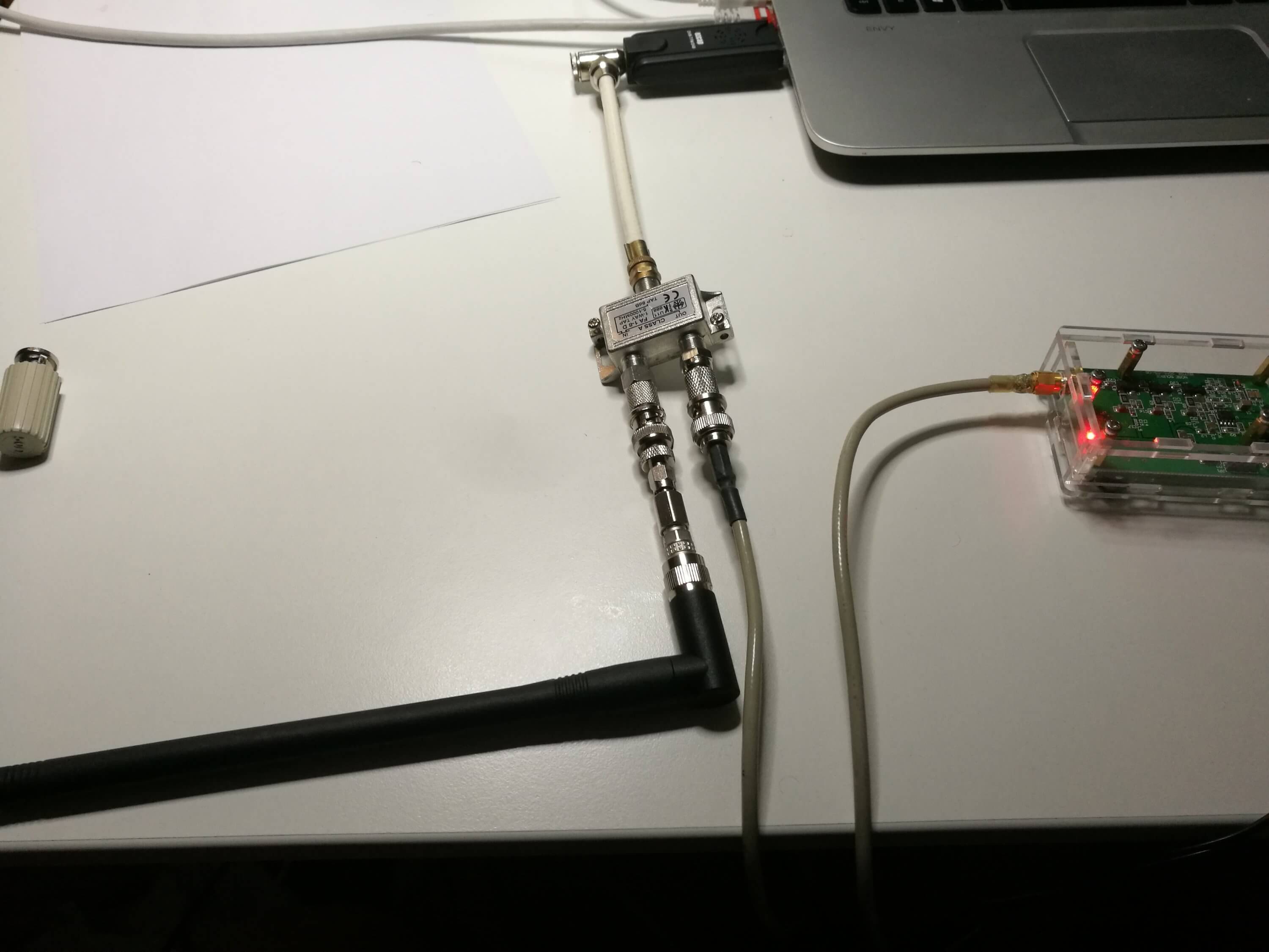
Tried this with two cheap tv taps from one local store. -8dB and -20dB taps. Tried to test home different home made antennas (ground pane quarter-wave monopole (433, 1090), QFH for 137 MHz, collinear 1090). Antenna connected to input via short coax, noise source to output and v2 dongle to tap.
The result is quite similar for both tv taps. But if I change the length of coax between input and antenna resonant frequency changes (for example 450 MHz for short coax and 433 for a bit longer). Tried different coax length – the resulting plot are very, very different.
What am I doing wrong (I’m not good in all this radio stuff, just trying to reproduce some tutorials from this blog)?