Using an RTL-SDR and moRFeus as a Tracking Generator to Measure Filters And Antenna VSWR
As Outernet is currently having a sale and selling their their moRFeus product at only US $99 (see next post for details - or simply use coupon code "rtlsdrblog" on their checkout - valid until Saturday 09 May 18), we thought that we'd show an interesting use for the moRFeus when combined with an RTL-SDR.
Outernet's moRFeus is a signal generator and frequency mixer that can be controlled either by it's built in LCD screen, or via software on a Windows or Linux PC. It can generate a clean low phase noise tone anywhere between 85 to 5400 MHz. Because it can be computer controlled it is possible to use moRFeus as a tracking generator for characterizing filters and measuring antenna SWR. A tracking generator is just a signal generator that can be set to output at the same frequency that the measurement receiver is tuned to.
In the past we've posted a tutorial showing how to use a wideband noise source for measuring filters and antenna SWR. However, if available, a tracking generator is usually preferred over a noise source. A wideband noise source outputs high power at all frequencies, and so can easily overload an RTL-SDR causing reduced dynamic range and accuracy in measurements. This is especially the case when measuring bandstop filters as they pass all frequencies, apart from a small blocking band. Since so much noise gets through to the dongle, dynamic range is reduced.
This post shows how to use the moRFeus as a tracking generator together with an RTL-SDR for making RF measurements. This could be called a scalar network analyzer. The set up uses GQRX and a Python script, but in the future it is possible that someone may develop a standalone app.
Equipment Required
- A directional coupler like the minicircuits ZFDC-20-5, or an RF Bridge with 50 Ohm dummy load.
- moRFeus or other computer controllable wideband signal generator.
- An RTL-SDR
- A ~20dB attenuator
Since the output of the moRFeus is quite strong, an attenuator is required to keep signal levels low enough to not overload the RTL-SDR.
The cheapest RF bridge we've found is available on eBay for about $7. With an RF Bridge you'll need a 50 Ohm dummy load as well to connect to the 'REF' port. Directional couplers seem to work more accurately however, and second hand minicircuits ones can often be found on eBay. A $2 TV 'tap' is also a directional coupler, and may also work, although we have not tested this.
Software Setup
In this tutorial we're using the method first described by 'LamaBleu' in his post to the Outernet forums. The method uses Linux and involves reading power levels from the RTL-SDR by using GQRX and it's remote telnet connection capabilities. The telnet command "F freq" can be used to change frequency in GQRX, and the command "l" can be used to read out the current power level in dbFS.
To control moRFeus we use Outernet's official "morfeus_tool", which is a command line based tool.
A basic Python script was written to set the frequency in moRFeus and GQRX at the same time. After a 500 ms settling time the power level is measured and recorded in a CSV file, then the script iterates to the next frequency. We iterate at 1 MHz intervals.
If you have a moRFeus and want to try this project out, copy and paste the script from pastebin, and name the file morfeus_scalar.py. Place the morfeus_scalar.py file and the morfeus_tool_linux_x32 tool into the home folder.
To get the software started:
- Open GQRX and connect the dongle and required RF components for the test (shown below).
- Set the RTL-SDR gain to zero or just low enough so that the signal doesn't cause overload (moRFeus signal levels are fairly high).
- In the GQRX GUI ensure that the "Remote control via TCP" button is pressed in. (Looks like two computer screens).
- Edit the Python script and choose the frequency range that you'd like to scan by setting variable FREQ_MIN and FREQ_MAX.
- In a terminal run "sudo python morfeus_scalar.py".
- When the script completes you'll have a file "out.txt" which is a CSV file of frequency and signal power levels.
Characterizing Filters
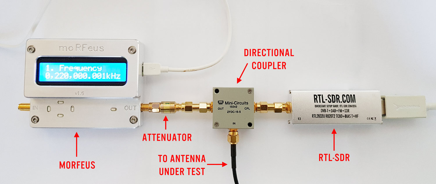
To characterize a filter (find the response of a filter) simply connect the system like so:

- But first connect just the moRFeus, attenuator and RTL-SDR together.
- In GQRX increase the gain until just a few dB before the RTL-SDR overloads and starts showing signal images. This will maximize the available dynamic range.
- Run an initial calibration scan with morfeus_scalar.py. Save the results in out.txt into a spreadsheet.
- Connect the filter in the RF chain, and then run a second scan with morfeus_scalar.py. Save the results into another column in the spreadsheet.
- Subtract the calibration scan results from the filtered results. Plot the resulting values using the spreadsheet software. This will show the response of the filter.
Download Example Spreadsheet (.xls) (.ods)
Measuring Antenna VSWR
VSWR is a measurement that can be performed on antennas to determine how well matched an antenna is to (normally) 50 Ohms. Lower VSWR values are better, with a VSWR of one being the best. To measure VSWR connect the system up like in the following photo:
- First run a scan with the antenna disconnected and record the out.txt results into a spread sheet.
- After the first scan completes, run the scan again with the antenna connected, and save the out.txt results to the spreadsheet.
- Subtract the antenna disconnected power levels from the antenna connected power levels to determine the return loss.
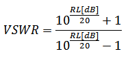
- Using the SWR formula below to calculate the SWR.
Download Example Spreadsheet (.xls) (.ods)
Results and Measurement Accuracy
Here we compare the results measured by a commercial VNA (miniVNA Tiny), versus an RTL-SDR noise source measurement system, versus one using the moRFeus as a tracking generator.
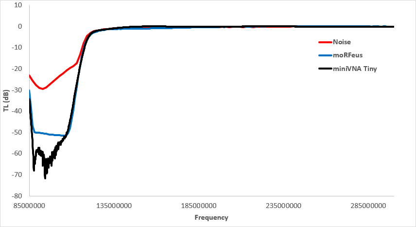
BCFM Bandstop
When measuring a bandstop filter like our RTL-SDR Blog BCFM Bandstop filter the noise source really struggles to produce an accurate result since the majority of noise over the spectrum gets through, thus overloading the dongle. It is only possible to get the rough shape of the filter.
The moRFeus tracking generator can determine the attenuation up to the maximum dynamic range of the RTL-SDR, which is about 50 dB. The VNA gets the true attenuation which is over 60 dB.
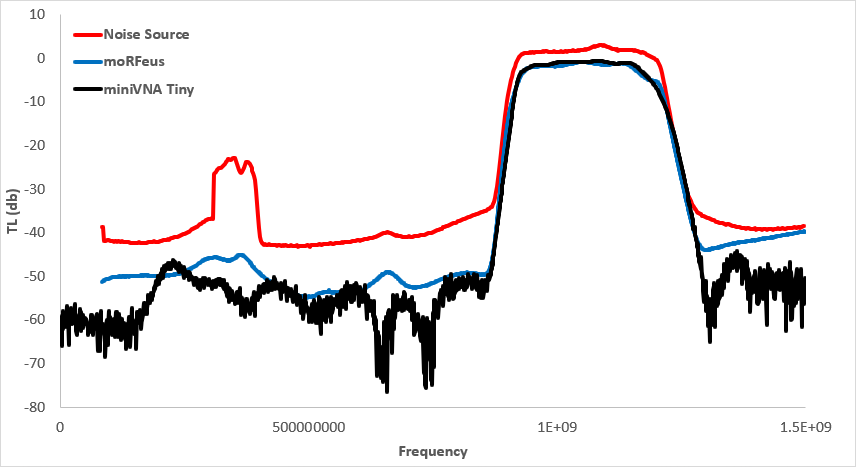
1090 MHz Band Pass Filter
Here we measure the FlightAware 1090 MHz ADS-B filter. The noise source isn't quite able to utilize the full dynamic range of the dongle, but it's better than with the band stop filter. There is also a odd glitch that occurs at around 300-400 MHz which seems to be something related to overload of the dongle.
Again moRFeus as a tracking generator gets close, but not quite down to the 60dB+ attenuation that this filter provides.
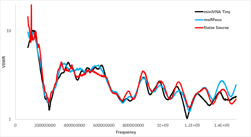
Antenna VSWR
Here we measured the VSWR of a dipole with 30 cm elements. In theory the resonant point should be around 238 MHz.
Both methods quite clearly show the resonant point of the antenna quite accurately, and are very close to the VNA's measurement. But the moRfeus tracking generator method does appear to follow the VNA's results slightly closer. The noise source method also has a bit of trouble when it comes to accurately measuring larger VSWR values, since the return loss is closer to zero, requiring more measurement accuracy.
One thing to consider is that a scan from 85 - 1500 MHz with the moRFeus and with a 500 ms settling time takes about 15 minutes to complete. Running the scan faster gives gibberish results as it seems that the measurement can't settle fast enough. A standard rtl_power scan with 2 MHz bandwidth and noise source only takes about 30 seconds, and the commercial VNA is done in 10 seconds.
Download Example Spreadsheet (.xls) (.ods)
Conclusion
We've shown that the moRFeus can be used as a low cost tracking generator together with an RTL-SDR for characterizing filters, and for measuring the VSWR of antennas. Compared to the method of using a noise source, using the moRFeus as a tracking generators gives better results that are closer to that of a commercial VNA.


the link for “morfeus_tool” needs to be updated to https://archive.othernet.is/morfeus_tool_v1.6/
(it’s not OUTERNET any more)
also see https://github.com/LamaBleu/moRFeus_GUI
Very interesting.
Well done Outernet on creating an interesting device.
Could I use a VGA to USB3 FL2k transmitter as the signal source rather than a Outernet Morfeous. It would radically reduce the cost of the hardware to build a software drive VSWR analyzer.
Hi
That is a great idea 🙂
Hi, thank you for this very nice and long tutorial showing what we can do, even with cheap devices.
Since my post on outernet.is, I also found possible to replace GQRX by rtl_power_fftw to get signal level.
I pasted an example here : https://pastebin.com/2UsN1XuK . Bash and gnuplot 🙂 Looks also good but I didn’t take time to investigate a lot, have to confirm rtl_power_fftw parameters.
I also made few tries using rtl_tcp and csdr, and this looks really promising.
https://imgur.com/39gBNbl : outernet SDRx 1.10
https://imgur.com/kELtyT9 : Thumbsat vs rtl-sdr.com v3
Excellent work!