Grid-2-Audio: Analyzing the Mains Electrical Grid Waveform with a PC Soundcard
Over on Hackaday and Hackaday.io we've seen an interesting project by David Scholten called "Grid-2-Audio". The project's goal is to build a safe device for monitoring the mains electrical grid waveform via a power jack and PC soundcard. This is essentially an SDR, with the soundcard acting as the ADC for the 50Hz grid signal, and Grid-2-Audio acting as a safety isolator and signal preconditioner. About why you might want to monitor the mains power signal, David writes:
There is a lot to be observed from the waveform of the electrical mains. Harmonics, transient changes, periodic fluctuations, frequency shifts, impedance, power line communications - These all give clues as to the state of the country's electrical transmission system (or what loads your neighbour has connected). Platforms like MATLAB allow for the easy analysis of waveforms through powerful software tools, but only once the signal has been acquired.
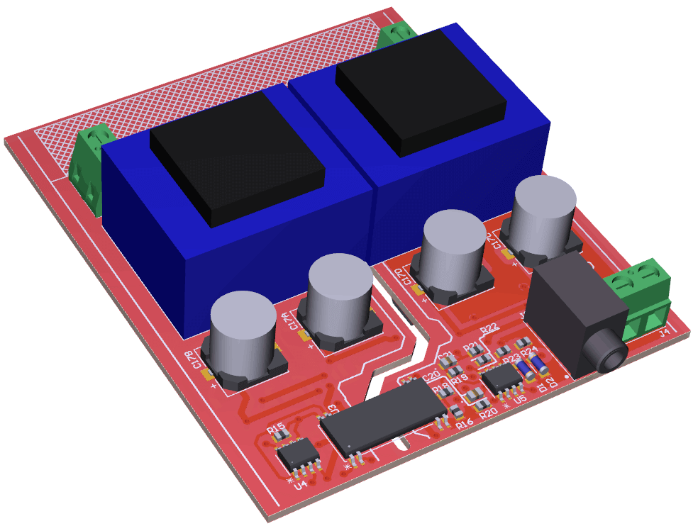
The final product will be a black box with mains plug and a 3.5mm audio jack ready to plug into your soundcard. In order to make the device safe, mains isolation transformers are used as well as good PCB design practices that isolate live and safe areas on the PCB. In the design care is also taken to maintain signal integrity and to not introduce noise by ensuring that the power supply draws minimal sinusoidal current, and is in phase with the voltage.


or when available a digital oscilloscope like TEKTRONIX TDS3034C (can be used record IQ Files, however pricetag is about 30k$)?
My question is what is the intention of this project, since the frequencies and bandwidth of interest differ with source.
WHich sources are of interest, load generated interference on the 50hz/60Hz AC can come from within your own, (adjacent) home(s)/appartment(s), or from sources much farther away (generators, converter, lightning …).
While legacy generators motors would be short sparks, switching circuit adds depending on design more or less strong RFI on AC e.g. LED-Lamps, Powersupplies, or originate from data communication like Power Line.
Question to understand what the circuit is doing: what is the difference between using this interface and using a 2ch. low end pc oscilloscope ?