Tagged: hackrf

War Driving for DECT Devices with a HackRF and Android Device

Over on her YouTube channel SignalsEverywhere, Sarah has uploaded an interesting video showing her doing a wardrive for DECT devices, with an Android device connected to a HackRF, running her own Android version of DECT toolkit. In the past, we also covered her DeDECTive software, which is a fully DECT scanner and voice decoder for Linux and the HackRF.

DECT is a digital wireless protocol operating at around 1.9 GHz, which is typically used by modern cordless home phones, baby monitors, headsets, intercoms, and more. If you are unfamiliar with the term wardriving, this is when someone drives around in a vehicle and looks for interesting signals around the area. Wardriving is typically associated with mapping out the local WiFi environment and looking for security flaws, but it can apply to any signal.

During her wardrive, Sarah finds mostly VTech cordless phones, but a few other models like 'Binatone' and 'RTX' pop up, which she suspects are headsets, one possibly from a local McDonald's. She notes that only one active call was found, although the video has voice decoding stripped out for privacy reasons. She also notes that no encryption was found to be enabled on any device, despite DECT supporting it. The Android App also records the GPS position of any found DECT devices on a map.

War Driving for DECT Devices

Exploring the Art and Science of Spectral Painting with SDR

Thank you to Paul Maine, who wrote in and wanted to share some experiments he and Gary Schafer have been doing with spectral painting. Spectral painting is the art of drawing pictures directly on the spectrum waterfall, which a software-defined radio makes visible. Paul has written the post below:

What happens when radio technology meets digital artwork? The result is something fascinating called Spectral Painting—the ability to create images that appear inside the radio frequency spectrum.

Gary Schafer (@signalgalaxiesunlimited) and Paul “The SDR Guy” Maine (@paulmaine6433) have teamed up to explore this unique combination of software-defined radio, signal processing, and creativity. Together, they have created companion videos on Spectral Painting and released them at the same time, each approaching the topic from a different perspective. For the best experience, it is recommended to watch Gary’s video first, followed by Paul’s practical demonstration.

Gary begins the journey by diving into the theory behind Spectral Painting. Using GNU Radio flowgraphs and GNU Octave scripts, he explains how images can be transformed into signals and displayed within the frequency spectrum.

Paul then takes Gary’s GNU Radio flowgraph and GNU Octave scripts from theory into practice. Using multiple SDR platforms, he demonstrates how to transmit spectral images using both the HackRF and TRX-DUO SDRs. He then completes the process by receiving and displaying the images using several different SDR receivers, including the RTL-SDR V3, RTL-SDR V4, and Airspy HF+.

Together, these videos provide a complete journey—from understanding the science behind Spectral Painting to seeing it come alive on real SDR hardware.

Below is an example screen capture of Spectral Painting in action.

Spectral Painting Example

Start with Gary’s video to learn the concepts and signal processing techniques:

Creating Spectral Paintings using Gnu Radio Companion (and other open source tools)

Then watch Paul’s video to see Spectral Painting transmitted and received using real SDR equipment:

E30 Spectral Painting

InmarScope: An Inmarsat AERO and STD-C Decoder with Multichannel Decoding and Automatic Call Following

Over on the SignalsEverywhere YouTube channel, Sarah Rose has released InmarScope, a multichannel L-band Inmarsat decoder that connects directly to an RTL-SDR, Airspy, or HackRF. The software can receive and decode both aeronautical (AERO) and maritime (STC-C / EGC) traffic at the same time. Decoders are dropped directly onto the aligned FFT and waterfall by holding CTRL and left-clicking, and the software lets you stack Aero MSK (600/1200 bps), high-rate OQPSK (10500 bps), AMBE voice (8400 bps), and Inmarsat-C BPSK decoders side by side.

One of the more interesting features is automatic voice-call following. By monitoring the 10500 baud forward-link channels, InmarScope can receive C channel voice assignments and automatically retune the SDR to the assigned frequency, lock the carrier, decode and record the AMBE call, and then hop back to where it was. There is also a two-SDR mode that dedicates a second radio to voice with a live split-view spectrum so one radio stays on the P control channel while the other tunes to voice calls. For assignments that never get broadcast, there is also a Call Hunter feature that uses a squelch threshold to automatically drop the decoder when a call appears. When a call is playing, the built in flight map also decodes the aircraft hex ICAO address and looks it up on airplanes.live, showing the plane's position and route in real time.

Recent updates have added a community-editable band plan, message search and filtering, an IQ recorder that also captures the seconds before you hit record, and a web dashboard for browsing decoded data from a phone.

The software is completely open source on GitHub, and the C++ code can be compiled from source, or a precompiled Windows build is available on sarasforge.dev for $15, with Sarah's Patreon patrons getting it free.

We note that Inmarsat signals such as AERO and STD-C/EGC can be received with our RTL-SDR Blog L-band Patch Antenna, which is available in our store.

Multi-Channel Voice Following Inmarsat Decoder for Windows!

Decoding Inmarsat in 2026

OpenStint: An Open-Source RC Car Lap Timing System Using an RTL-SDR or HackRF

Thank you to Attila for submitting news about OpenStint, an open-source lap timing system for radio-controlled (RC) car racing that uses an RTL-SDR or HackRF One as its receiver. In RC racing, each car carries a small active near-field transponder that transmits a unique identifier on 5 MHz using BPSK modulation. A wire loop embedded in the track acts as the receiving antenna, picking up each transponder's signal only within a short distance, which allows the exact crossing point to be detected. OpenStint digitizes this signal with the SDR and performs the decoding and pass detection entirely in software, with sufficient accuracy for RC racing.

Professional timing systems work on the same principle, but rely on dedicated proprietary hardware and software, with even entry-level systems typically costing thousands of dollars. OpenStint is compatible with the transponders used by the vast majority of RC racing clubs (MyLaps RC3 and RC4), while also supporting its own fully open-source transponder design. A complete decoder can be built from inexpensive off-the-shelf components, typically consisting of an RTL-SDR dongle, a simple loop interface, and a laptop or even a Raspberry Pi 3. The software has also been tested with existing timing software including LapBeeps, RCGTiming, and ZRound.

Besides the decoder itself, the project documents an open-source transponder protocol, includes an ATtiny-based transponder reference implementation, and describes the signal processing used for reliable pass detection. Documentation and source code can be found on the OpenStint website and over on the project's GitHub page, with the open transponder design available here.

Atilla also sells the transponder boards on the OpenStint website's sales page for a reasonable €30/panel + shipping (8 pcs per panel), and notes that larger quantities can easily be manufactured by JLPCB.

AI-Disclaimer: We note that Claude is listed as a contributor to the code.

OpenStint: RC Car Lap Timing with RTL-SDR or HackRF

sdrrat: An SDR receiver Terminal User Interface for RTL-SDR & HackRF

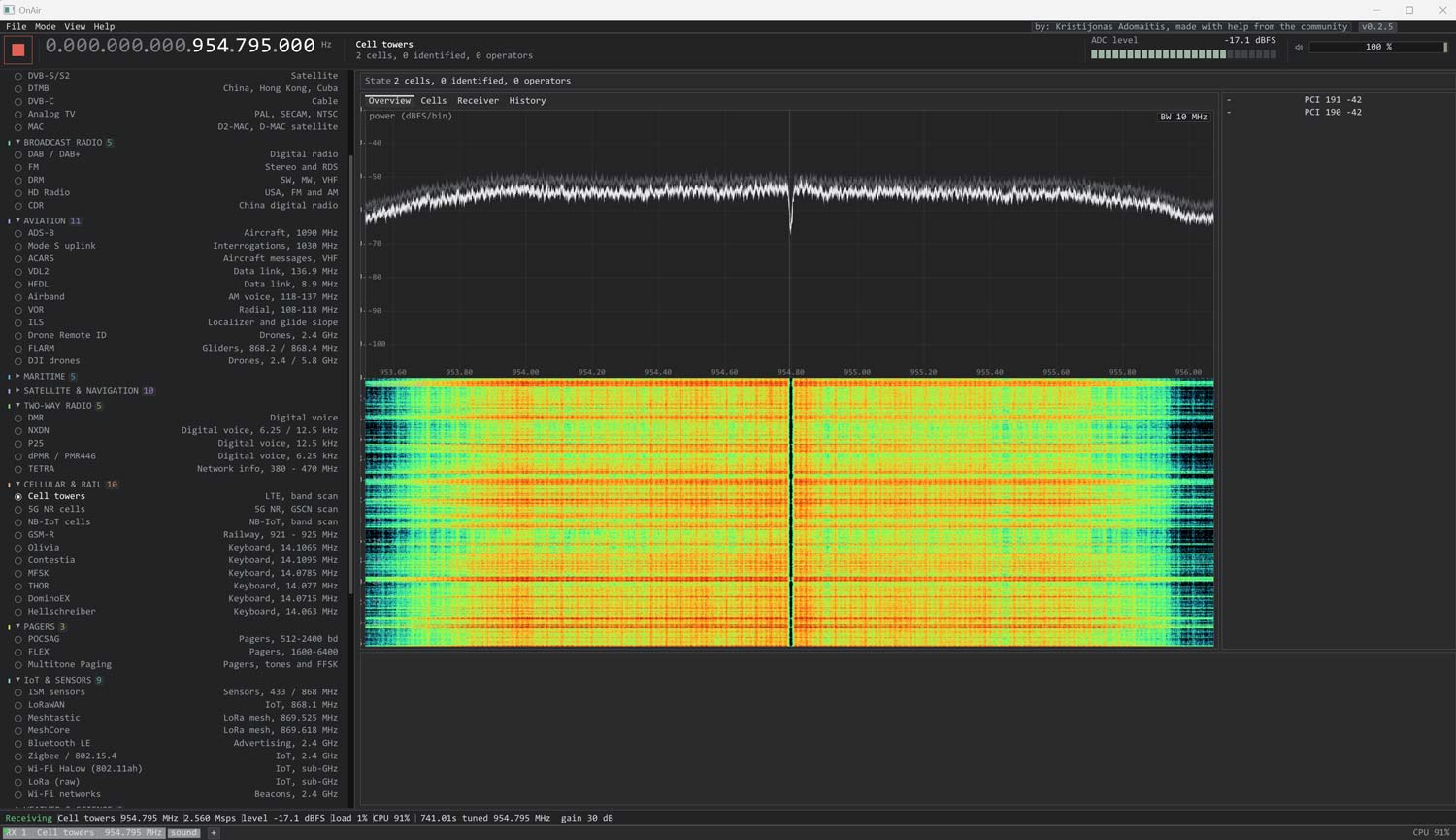
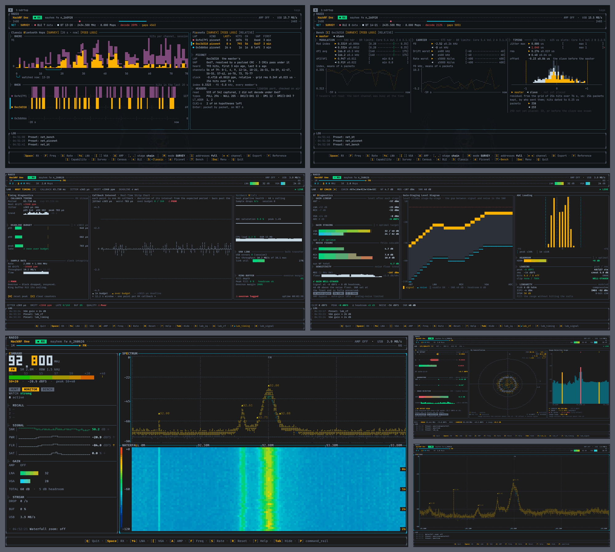
Thank you to qewer33, who has written in to share the release of his new Terminal User Interface (TUI) program for RTL-SDR and HackRF SDRs.  The program is called sdrrat, and it provides a complete TUI with FFT graph, waterfall spectrogram, VFO, and basic WBFM/NBFM/AM demodulation. 

qewer33 notes that the software is built with Rust, Ratatui, and FutureSDR and is completely free and open source. The code is available on GitHub.

sdrrate: TUI based SDR software for RTL-SDR and HackRF

P25-Survey: A Tool for Scanning and Logging P25 Control Channels with an SDR

Over on GitHub, programmer blantonl has released p25-survey, a Python tool that scans a frequency range with an RTL-SDR, Airspy or HackRF and identifies any P25 control channels present. For each one found, it logs the WACN, System ID, NAC, RFSS ID and Site ID, the full IDEN_UP band plan, neighbor sites with resolved frequencies, and signal quality metrics including RSSI, BER and decode rate.

The tool also has an optional RadioReference cross-reference mode that annotates results with the RR system name and site description, flags frequency offsets versus the database, and generates a Markdown submission report for data not yet in RadioReference. An auto-gain feature sweeps gain values on each confirmed control channel and recommends the optimal setting for your SDR and location based on BER.

P25 Survey Tool
P25 Survey Tool

Detecting Hidden GPS Trackers via Electromagnetic Unintentional Emissions with a HackRF

Researchers from Hunan University, Boise State, and UT Arlington have published a paper called "GPSBuster" (PDF link), demonstrating how a HackRF One can sniff out covert GPS trackers by their unintended electromagnetic radiation. Hidden trackers are hard to find since they only receive satellite signals and may store coordinates locally rather than transmit. Instead of looking for transmissions, GPSBuster targets side-channel leakage from the tracker's mixed-signal SoC, specifically the coupling between the quartz oscillator, local oscillator, and mixer used to downconvert the 1575.42 MHz L1 signal.

The team found that an active tracker leaks two characteristic spectra: a low band around 26 to 104 MHz and a high band around 1545 to 1625 MHz, each with a strong peak and evenly spaced harmonics. The low band reflects coupling between the quartz oscillator (typically 26 MHz) and the IF, while the high band contains LO plus IF spacing that always sums to 1575.42 MHz, giving a database-free detection rule. The setup consists of a HackRF, an NFP-3 near-field probe, and a 35 dB LNA. The use of the near-field probe means that sweeping the probe over an area to find the tracker is necessary, and the maximum detection range was 0.61 m.

Tested against the top 10 trackers available on a popular online marketplace, GPSBuster hit a 98.4% detection rate, working through plastic, cotton, canvas, and leather, and alongside phones, laptops, and speakers. It also extended to L1+L5 modules like the Quectel LC29H series, and even metal-shielded chips still leaked enough via PCB traces to be picked up.

Covert GPS Tracker Detection with a HackRF and Near Field Probe
GPSBuster Field Prototype

Saveitforparts: Receiving Artemis 2 Signals

Over on the saveitforparts YouTube channel, Gabe has recently posted two videos where he attempts to receive the Artemis 2 signal. His setup consists of a surplus satellite dish inside a geodesic radar dome at his "Sandland" radio observatory, a 3D-printed feed, a HackRF One SDR, and various LNAs, including a dedicated S-band unit from LMA Scientific. He used GPredict for tracking and SDR++ for spectrum analysis, targeting the expected downlink frequency around 2216.5 MHz.

The main challenges were the capsule's low elevation angle from his location in Minnesota, rapidly changing orbital elements that made TLE-based tracking unreliable during the trans-lunar injection burn, and the fact that all telemetry is encrypted. During his first overnight session, he was only able to detect what appeared to be an extremely faint carrier at approximately 2216.49 MHz, which is consistent with the expected Doppler-shifted frequency, which disappeared when the dish was moved off-target. In a second session timed to catch a handover between NASA's Goldstone and Canberra Deep Space Network stations, he received a noticeably stronger carrier signal and even observed sideband activity, though still not strong enough to resolve any modulation detail.

He notes that NASA's original citizen science RFP called for ~9 meter dishes, far larger than his ~2.5 meter setup, and that the capsule also uses a laser communications system for high-bandwidth data. The Canadian Space Dashboard and DSN Now websites proved useful for predicting optimal observation windows during ground station handovers.

Can I Overhear The Artemis II Moon Mission With SDR?

Listening To Artemis II's Return To Earth With DIY Satellite Station