RTL-SDR.COM GOES 16/17 and GK-2A Weather Satellite Reception Comprehensive Tutorial
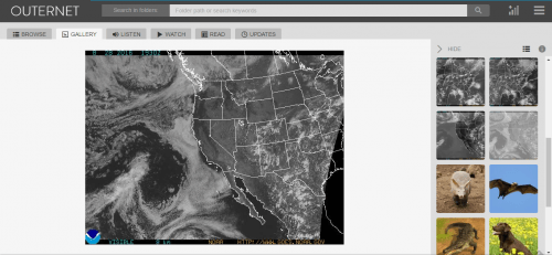
GOES 16/17 and GK-2A are geosynchronous weather satellites that transmit high resolution weather images and data. In particular they are far enough away from the earth to be able to take beautiful 'full disk' images which show the entirety of one side of the Earth. As these satellites are in a geosynchronous orbit, they can be counted on to be in the same position in the sky at all times, so no tracking hardware is required and images can be pulled down constantly throughout the day without having to wait for a polar orbiting satellite to pass over like you would with the NOAA APT or Russian Meteor satellites.
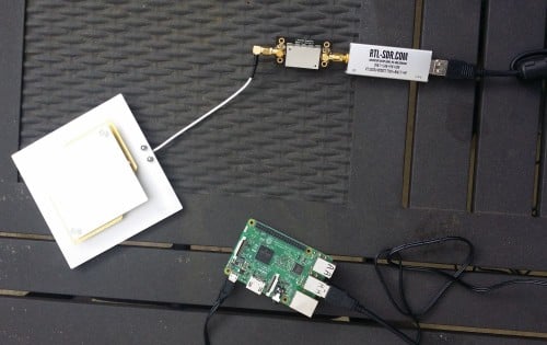
With a low cost WiFi grid dish antenna, LNA and RTL-SDR dongle, any home user within the footprint of one of these weather satellites can receive and decode live images directly from the sky. Setting up a station is overall not too difficult, but it can be a bit fiddly with a number of steps to complete. Below is our comprehensive guide. We'll show how to set up a self contained Raspberry Pi based system with goestools (free), as well as a guide for the Windows PC software XRIT decoder (US$125).
We've attempted to make the tutorial as newbie friendly as possible, but we do need to assume basic RF knowledge (know what antennas, SDRs, coaxial, adapters etc are), basic Linux competency for the goestools tutorial (using the terminal, using nano text editor), and basic Windows competency for the XRIT decoder tutorial (unzipping, editing text files, running programs).
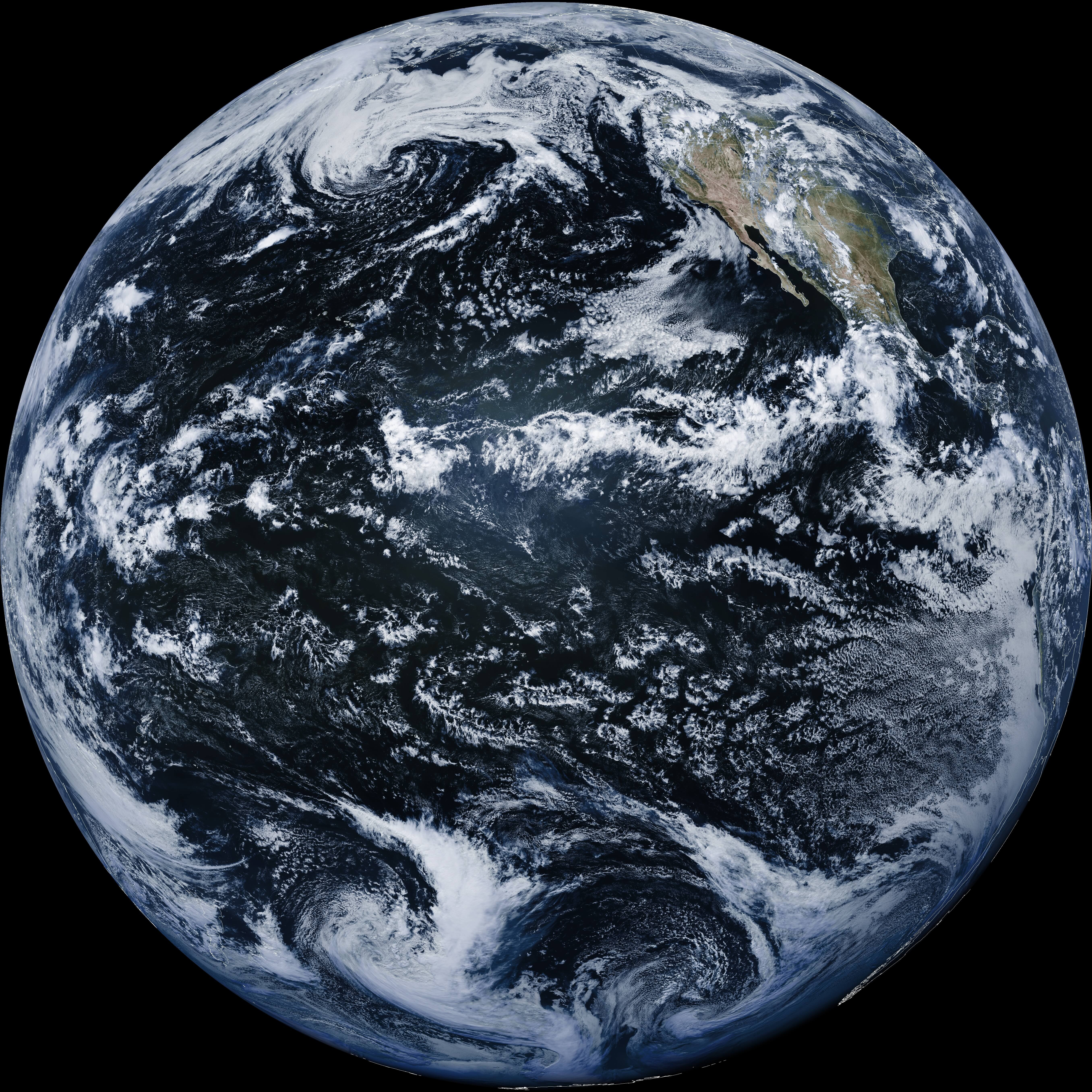
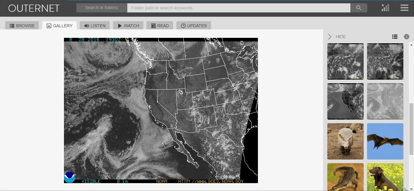
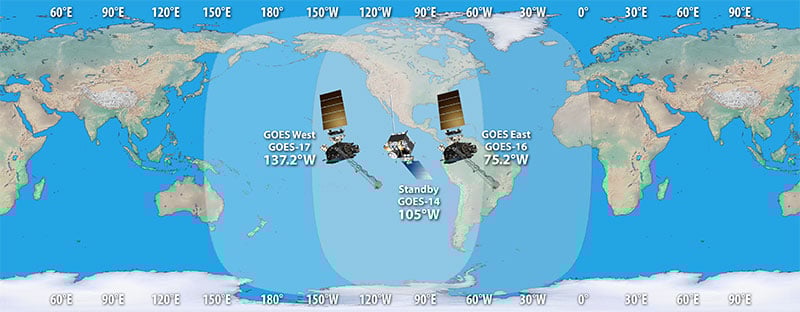
There are two fourth generation NOAA GOES satellites that are currently active, GOES-16 and GOES-17. These transmit HRIT signals, and also transmit shared data from the older third generation GOES 15, and Japanese Himiwari8 satellites. At the moment GOES-16 and GOES-17 are producing full disk images every 30 minutes, and close up "mesoscale" shots of the USA every ~15 minutes. GOES-16 (aka GOES-R) and GOES-17 (aka GOES-S) are also known as GOES-EAST and GOES-WEST respectively. At least one of these satellites can be received from North/South America, Canada, Alaska/Hawaii, New Zealand, Eastern Australia and some pacific islands.
There is also the older generation GOES-15 and GOES-14 which have been placed in standby orbits. These transmit LRIT signals which provide images at a slower rate.
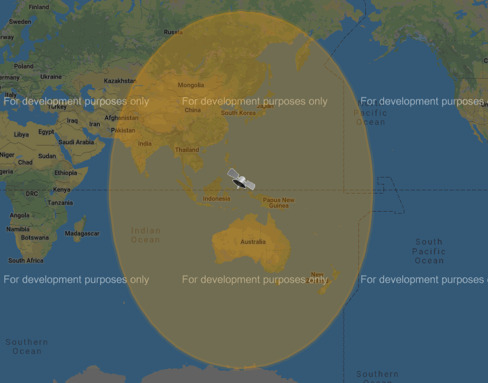
There is also the Korean GK-2A (GEO-KOMPSAT-2A) satellite which is very similar to the GOES satellites. GK-2A covers countries like India, Asia, Australia, New Zealand and parts of Russia. Note that you may have previously heard of the COMS-1 satellite which used to cover this area. Since July 2019 COMS-1 was replaced by GK-2A. Unlike GOES, GK-2A images are encrypted. However it has been found that "sample" encryption keys found online in demo code work just fine.
GK-2A contains both LRIT and HRIT channels, but at the moment only the LRIT channel can be decoded with the currently available software. The LRIT channel sends full disk IR images every 10 minutes in 2200 x 2200 resolution. Compared to the 5424 x 5424 resolution GOES full disk images, this is smaller, but still large enough to be interesting.
Note that even if HRIT decoding is added by the current software, you would require an Airspy or other wideband SDR as the GK-2A HRIT signal bandwidth is 5 MHz. Also since the HRIT bandwidth is so wide, the signal strength is reduced, meaning that you'll need a larger dish. People who have received the HRIT signal note that a 3M+ sized dish seems to be required.
You might ask why bother receiving these satellite images directly, when you can get the exact same images from NOAA at https://www.star.nesdis.noaa.gov/GOES/index.php. Well, you might want to set up your own station to be independent from the internet, or you live in a remote location without internet, or maybe just for the fun and learning of it.
To set up a receiver for GOES 16/17 HRIT or GK-2A LRIT you'll need to purchase a dish antenna such as a cheap 2.4 GHz WiFi antenna, an RTL-SDR, GOES LNA, and a Raspberry Pi if using goestools, otherwise a Windows PC can be used. The total cost could be anywhere from $150 - $200 depending on what pieces you already have available.
Before we start the tutorial, you might want to use an augmented reality Android app like "Satellite-AR" to get a rough idea of where either GOES 16/17 or GK-2A (GEO-KOMPSAT-2A) is in your sky, and if receiving them is even feasible for your location. You'll need to find an area on your land where you can mount a small satellite dish with an unobstructed line of sight view to the satellite (no trees or buildings can be blocking the signal path). If the satellite is low on the horizon (below 25 deg elevation), then things get a little more difficult as you have more obstructions and a weaker signal. But it can still be done, and we're able to routinely get good results at 24.5 deg elevation.
Note that for Europe and Africa, unfortunately there are no satellites that can be received easily with an SDR and LNA. But you might instead be interested in the EUMETCAST service, which can be received from EUTELSAT 10A (Ku band), Eutelsat 5 WEST A (C Band) and SES-6 (C Band) . To receive this service you'll need a DVB-S2 receiver and a satellite dish with appropriate band LNB. You also need a license keys and software which all together cost €100. EUMETCAST reception is not covered in this tutorial, instead see this video.