Tutorial on Properly Positioning a Preamp (LNA) in a Radio System
Radio blogger Anthony Stirk has made a post on his blog explaining some critical concepts behind understanding why it is important to position a low noise amplifier (LNA) near the radio antenna, rather than near the radio. In the post Anthony explains how the Noise Figure (NF) and linearity (IP3) of a radio system affect reception.
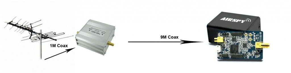
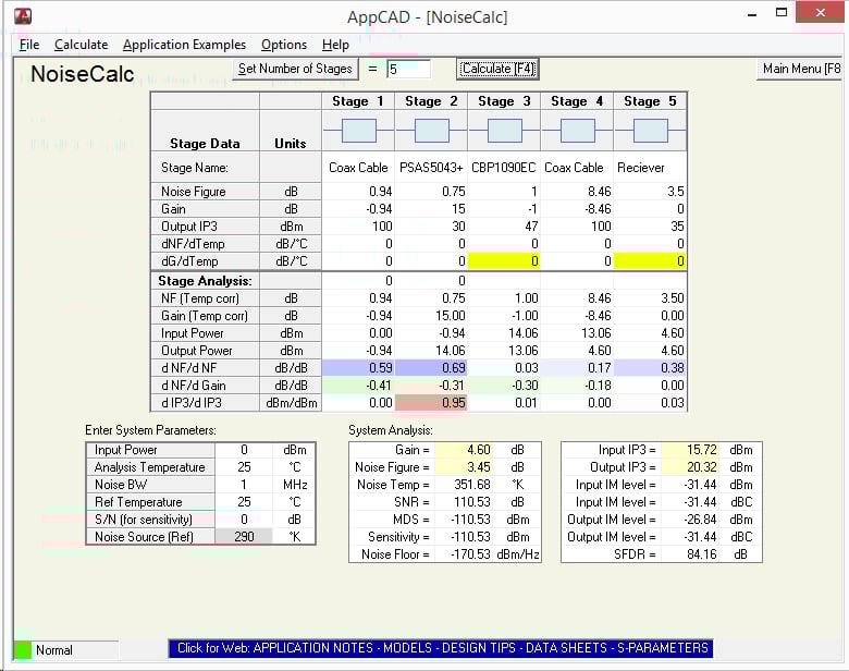
Using the free AppCAD RF design assistant software, Anthony explains how the noise figure of a system increases with longer coax cable runs, and how it can be reduced by placing an LNA right next to the antenna. He also explains why the sensitivity of the radio won’t increase if the LNA is placed close to the radio instead.
In addition to this, he also explains why adding more LNA’s to a system decreases the linearity (IP3) of the system and that if the receiver has a built in LNA that the system linearity can be severely degraded by adding extra LNA’s, causing easy overloading and intermodulation. In conclusion Anthony writes the following:
In summary, a setup with a good antenna system connected to a receiver with a built in LNA:
- May not benefit from having a preamp at the antenna.
- The presence of a built in LNA is detrimental to the linearity and may degrade the signals.
So in conclusion:
- Put the preamp as close to the antenna as possible.
- Receivers with a built in LNA may not get the most out of an antenna system or preamp.
- Proper gain distribution guarantees better performance than one-size-fits-all solutions, both in terms of sensitivity and strong signals handling.


I am attempting to operate an Airspy R2 dongle in a radio telescope that is located 75 feet from the radio shack. My dish antenna feed chain is as follows. Antenna probe-LNA-Band pass filter-Airspy R2-75′ shielded ethernet cable-PC. I was told that this arrangement might be better for getting a low-noise signal to the PC rather than using 75′ of coax between the LNA/BPF and the Airspy at the PC. Based on the discussion above I gather this may be incorrect. Comments very appreciated…
What would be the detriment to inserting the preamp downstream from the antenna tuner and feeding the amplified signal into the mixer? First blush would seem to make the antenna tuner reduce all signals outside the tuned frequency bandwidth and amplify only within the tuner bandwidth. ???
Nice article that explain general problems and how to cure them in the signal chain. This was needed to be written and explained the simple way using the “cheap” and affordable equipment. More over, the Ernest comment is in place indicating the roots of the problems using the same simple equipment.
I would like to point a few things that I see not correct in the article to have the understanding even better and the calculations in the signal chain correct. Most probably the mistake from the author was done not intentionally and all following the hardware data sheets or unit specifications that are mostly written by the marketing guys and not by engineers.
The author of the text properly concludes that the best IP3 point of the SDR receiver (+35dbm) is achieved when the gain is set to minimum, in this case 0 db gain for the tuner. At the same time author forget that setting the gain to 0dB the NF (noise figure) is not the minimum but the maximum for the same tuner. This value is much higher than the 3.5dB (let say range 16 to 20dB NF) This error is affecting all the AppCAD calculations done in the article a lot. This is how the tuner is made and behave decreasing the gain to zero. On the other side, most of the users tried to set the gain to zero are aware of the performance and how deaf is the receiver at that point.
To prove my statement about the correlation of the gain and NF for the R820T used tuners you can check the early Leif, SM5BSZ series of videos where he measure and compare the performance of the mostly used receivers where the NF is affected by the set receiver gain. Even in the best case scenario he finds out that the noise of the receiver using only R820T with the highest gain set is never bellow the 5.5dB.
Taking in account this figures and you will be fine with the article.
Have fun,
Adam
The calculations are correct, but I agree that measured figures would make much more sense than the marketing BS. For completion, I think the article needs another calculation with worst case NF scenarios where a LNA near the antenna still beats integrated non-switchable one.
As with any good receive amplifier, you get a far better S/N ratio when you design separate amplifiers for each band you wish to focus on.
Wide band amplifiers can not make adequate use of low noise figures, nor frequency dependent filtering, unless you settle for a broad band design.
Even with GaAs FET designs, you need to ensure stable operation, without introducing problems such as self oscillation, or IMD. PIM only affects antenna systems such as fiberglass collinear designs, where several elements are stacked, and fed ‘corporate’ style. Loose connections, cracks and faulty construction can cause antennas to act as diodes, rectifying signals, and rebroadcasting those as IMD/harmonics.
Gain stages might also overload the receiver front end, especially in moderately low cost systems, such as the common USB RTL-SDR dongle. Let’s face it, they have very little filtering, and are so wide band, that this alone, is an open door for spurious and other damaging signals to cause havoc. You may have already noticed that almost anything that is transmitting nearby, causes these radios to go deaf and swamp. This is due to lack of proper filtering in the receive chain, and also causes selectivity to take a hit also.
Too much gain causes desense, and you might have to add some attenuation after the pre amp to get this under control. Do NOT place any attenuator in the receive chain before your amp. The weak signals will be lowered in strength by the amount of attenuation added, so the rule of thumb is to start at the lowest number, such as a 1 dB pad, and move up, only if your problem remains. With video systems, overload is seen as ‘bloom’, where colors are far more intense in level. This is front end overload in action.
With voice systems, this overload causes garbled audio, muffled audio, and sideband noise on adjacent channels. Occupied bandwidth should never be set to maximum, as a 12.5 kHz. channel spacing should never have a full 12.5 kHz. signal on it, but close, which is why the audio bandwidth is adjusted for 2.5 kHz. The job of the filters are to limit the signals getting in, pass the desired one, and reject the others.