RTL-SDR Direct Sampling Mode
The RTL-SDR software defined radio can be told to run in a mode called "direct sampling mode", which with a small hardware mod allows the dongle to tune to the HF frequencies where ham radio and many other interesting signals are found. This means that no upconverter circuit is required.
However, the difficulty with direct sampling is that a hardware modification to the dongle is required. Also, the performance can not be expected to be as good as an upconverter without the addition of extra filtering circuits. RTL-SDR Blog V3 Note: Note that our RTL-SDR Blog V3 already has the direct samping mod done and built in, so no hardware modifications are required for those units! Just see the V3 users guide for information on activating direct sampling mode.
The direct sampling mode was originally discovered and discussed in this Google groups thread.
Examples
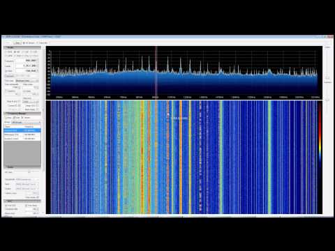
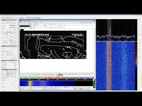
YouTube user Superphish was able to receive HF AM broadcast radio, and a decode a HF weather fax signal at 5.8MHz using the direct sampling mod.
Hardware Mod
The hardware mod is quite simple for someone with good soldering skills. It involves opening the dongle casing, and soldering a "random wire" or "long wire antenna" to pin one or pin two (or 4 or 5) of the RTL2832U chip. This allows RF signals to directly enter the RTL2832 chip by bypassing the tuner chip. Even a short wire a few centimeters long will be sufficient for picking up broadcast AM stations. For ham signals and international broadcasts, a longer wire placed up high is probably required. Care must be taken with the mod as this bypasses all electrostatic discharge (ESD) protection.
Pin one and two are located below the circle indentation on the RTL2832U chip. It might be easier to solder the wire to one of the two capacitors which are connected directly to pin one and two.

Some more useful images of pin layouts can be found at superkuh's RTL-SDR blog post.
If you are using an R820T or R820T2 tuner it may be best to use pins 4 or 5 for this mod as they are actually unused due to the architecture it uses. This will allow you to use normal quadrature sampling as per normal for VHF and UHF frequencies and direct sampling mode as well. The problem with these pins is that they do not have a capacitor connection, thus making them very hard to solder to.
Software Settings
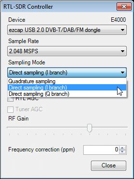
Activating direct sampling mode requires a software driver adjustment. Luckily, SDRSharp has this adjustment as a built in option. In SDRSharp, go to the configure menu, and change the sampling mode to "Direct sampling (I branch)", or "Direct sampling (Q branch)". The I branch corresponds to pin one/pin two, and the Q branch corresponds to pin four/pin five.
If a wire antenna is connected to any one of these pins, and the correct direct sampling branch is selected, you will be able to receive signals between 0 - 14.4 MHz. Frequencies between 14.4 and 28.8 MHz can also be received by using a band pass filter.
Balun/Matching Transformer Improvement
Since the RTL2832U uses two pins to create a differential input (one pins input is subtracted from the other), a balun or matching transformer can be used to connect both pins one and two to an HF antenna that is not just a simple random wire antenna. Essentially this improvement involves finding or winding your own balun, and connecting the balun inputs to both pin one and two (or four and five), and the other end of the balun to your antenna. Here is a pdf file by mikikg showing schematics for this modification.
Here is a blog post by Dekar who used a transformer from an old ADSL modem as the balun. A blog post here and also another here in Japanese show mods where the balun transformer was wound manually. Another site in Italian with a lot of useful images is here. He used a 4:1 self wound toroid as the balun and got what looks to be good results. Google translate can be used to translate the pages, but the images are the most important things here.
Although 4:1 balun's work okay, the actual input impedance is much higher than the expected 200-250 Ohms. In actuality it is around 3,330 Ohms, according to measurements made by an RTL-SDR experimenter Martin. Since a wideband 66:1 matching transformer does not exist, the current recommendation is to use the http://194.75.38.69/pdfs/T16-6T-KK81.pdf 16:1 matching transformer. This is about the closest to a wideband 66:1 transformer that we can get. One experimenter, Robert found that he had about a 16 dB - 19dB improvement in signal levels when using the Minicircuits T16-6T-KK81 16:1 transformer, when compared to a 4:1 transformer.
If you don't want to use a balun then it can also help to connect a 1 nF to 100 nF capacitor to ground on the unused pin.
Other Improvements
Most experimenters of this mod find that FM interference is a problem and thus low pass filters are necessary. The Italian mod page shows schematics and images of a 60 MHz low pass filter combined with the direct sampling mod. His results show significant improvements in out of band signal rejection with the low pass filter.
Some users also report that adding in a low noise amplifier (LNA) can help improve reception. A good Reddit thread discussing improvements to this mod can be found here.
Instead of using two antenna inputs, one for HF and one for VHF/UHF it is also possible to create a diplexer. This allows you to use one antenna port for both the direct sampling connections, and the standard VHF/UHF connections. See Martin's post for information on how he built his direct sampling diplexer on an RTL-SDR dongle.
Direct Sampling with No Hardware Modifications (No-Mod)
There is now an experimental driver by Oliver Jowett which allows tuning down to 13 MHz and sometimes even lower down to 1 MHz on a R820T RTL-SDR. When coupled with an LNA and low pass filtering this modified driver can work very well, but not as good as with an upconverter or hardware direct sampling mod. It is also reported that the R820T2 tuner works much better than the R820T tuner with this mod due to its wider filters.
There is also another experimental RTL-SDR driver by tejeez which enables a similar mod that allows HF tuning, but it works through a different mechanism. Most reports say that it is not as good as Oliver Jowetts mod, but it could possibly work better for broadcast AM frequencies. See a post about this mod here.
 If you enjoyed this tutorial you may like our ebook available on Amazon. The Hobbyist's Guide to the RTL-SDR: Really Cheap Software Defined radio. |


Hi, I want to share schematics of my balanced preamp for direct sampling with (optional) Butterworth low-pass fillter:
Note, that its input impedance is ~24 Ohm
Sorry forgot to do some corrections:
1) R9 is not a part of amp, but a load equivalent of RTL chip
2) forgot to put couple of load decoupling capacitors serial with R7/R8. Something 2nF .. 22nF will be fine there.
The link doesn’t work, you could update it.
Why does there need to be a special direct sampling mode in software? The pin that you solder the antenna wire to for the direct sampling mod, is part of the normal signal path. Just disconnect any antenna that you have on the device’s normal signal input, to make sure that no down-converted signal is present on these pins, and then in the software tune to any frequency (doesn’t matter what frequency you set, because no signal is coming into the device through the main signal input). Direct sampling mode requires (unless I’m mistaken here) absolutely NO software mod, ONLY a hardware mod.
The direct sampling mode disengages the code that controls the auxiliary tuner.
You may count me as a successful user of the patch. My dongle (with T2 chip) no longer stops at 24MHz. I have been listening to the Michigan and Ontario QSO parties on 40M, 75M, and 80M CW and SSB this weekend with a short random piece of wire as an antenna. On those bands, it hears nearly as well as my FTDX1200 with the same antenna. It goes into the AM broadcast band but crashes around 1MHz. It has made the device vastly more useful to me. Thanks, Oliver Jowett!
Hello,
I would not adapt the impedance of the antenna connector to the 3.3K impedance of the RTL chip.
This will only result in a higher probability of overvoltage breakdown of the RTL chip, hi.
Entry impedances of semiconductor chips are high for allowing a number of units to be connected
in parallel (fan in); in the present case, 16 RTL units can be driven from a same 200 Ohm antenna,
to make up a simultaneous multichannel receiver.
Rather use a 1:4 current balun with a 200 Ohm termination resistor and a pair of rapid Schottky
diodes as an overvoltage protection.
73, Edgar, HB9TRU
I´ve got a stick from the great bay a week ago. As I had open it, there was a big supprise: Pin 4 and Pin 5 have got each a little soldering-point in the new layout. So it´s much easyer to connect the shortband with the Q-branch.
Happy weekend.
Could you point us at the listing for your dongle? I’d like to buy one with the extra pads, but the listings mostly don’t say that they have them.
http://www.ebay.de/itm/RTL2832U-R820T-USB-DVB-T-HDTV-Tuner-Stick-FM-DAB-mit-MCX-Antenna-Fernbedienung-/301640610172?pt=LH_DefaultDomain_77&hash=item463b2e717c
here is the link from my ebay order
Best regards JH
I was wondering if you could use a PT6 Pulse transformer to do the HF Modification?
We can’t seem to get the required transformer here in the UK, I can wind my own but it would be nice to have something better.
Cheers!
It’s not really necessary to do modification if You still want to just catch a little of long waves. I for example (for some reason) get some long frequency bands during day time. Examples are: 436.1khz (quite nice strong signal), 475.9khz (weak signal), 505.9khz (weak signal), 566 khz (weak signal).
How did I ahieve it? Simple, I made myself some random 0.5mm wire antennas in my garden going through my window and comming back (not really that long… 40-50 meters maybe if not less), also some coil-like thing on a small PVC pipe (a lot of turns) and loop-alike on old big speaker case (6 loops, 4cm spacing), then I connected it all together to experiment (not really a loop, just trying various combinations). Unfortunatelly results were of course… bad, for ranges RTL supports by default but suprisingly it opened the door to direct sampling without mod – at least a bit.
For some reason I did catch a bit of signals as mentioned above on I band without modification (maybe dongle heating is the result of this? not sure). Of course doing the mod will give You much more posibilities, but I can say that I also catch some other weak signals 73khz and below…