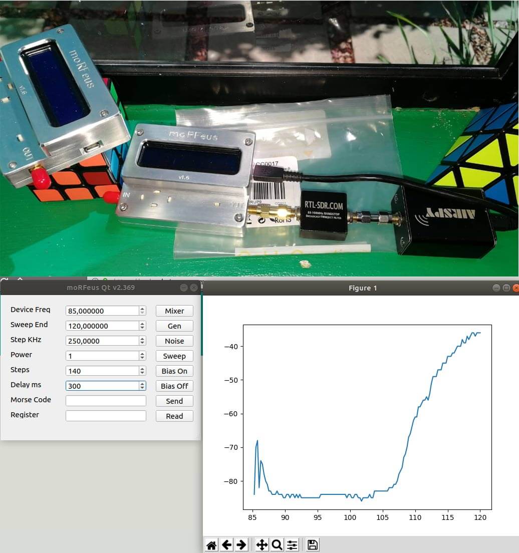
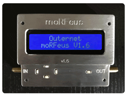
Outernet's moRFeus is a signal generator and frequency mixer that can be controlled either by it's built in LCD screen, or via software on a Windows or Linux PC. It can generate a clean low phase noise tone anywhere between 85 to 5400 MHz. Because it can be computer controlled it is possible to use moRFeus as a tracking generator for characterizing filters and measuring antenna SWR. A tracking generator is just a signal generator that can be set to output at the same frequency that the measurement receiver is tuned to.
In the past we've posted about some software developed by Ohan Smit, which allows a moRFeus to be controlled on a Windows/Linux PC via a nice GUI. Recently he's updated the software and it can now draw power (dbFS) graphs for characterizing filters when combined with an Airspy and TCP comms to GQRX. Ohan writes:
So when you press sweep, it detects if there is any TCP servers on port 7356 and if so tunes the radio and gets a power measurement and after the sweep is done, morfeusqt renders a graph on the fly.
It now also supports multiple devices, no configurations required. It just opens another window for the second device.
These features thus far work on both Windows 10 and Ubuntu 18.04.1, these are my two testing environments with GQRX and the Airspy.
Ohan also notes that he's working on several new features such as the ability to plot VSWR, remote control of the moRFeus via TCP, support for multiple SDR TCP protocols such as rtl_tcp, soapytcp etc, threading and progress bars, as well as possibly support for cheap Osmo-FL2K devices as a tracking generator.
You can follow his developments live on the Outernet forums.
moRFeus used as a tracking generator with an Airspy with the morfeusQT software
As Outernet is currently having a sale and selling their their moRFeus product at only US $99 (see next post for details - or simply use coupon code "rtlsdrblog" on their checkout - valid until Saturday 09 May 18), we thought that we'd show an interesting use for the moRFeus when combined with an RTL-SDR.
Outernet's moRFeus is a signal generator and frequency mixer that can be controlled either by it's built in LCD screen, or via software on a Windows or Linux PC. It can generate a clean low phase noise tone anywhere between 85 to 5400 MHz. Because it can be computer controlled it is possible to use moRFeus as a tracking generator for characterizing filters and measuring antenna SWR. A tracking generator is just a signal generator that can be set to output at the same frequency that the measurement receiver is tuned to.
In the past we've posted a tutorial showing how to use a wideband noise source for measuring filters and antenna SWR. However, if available, a tracking generator is usually preferred over a noise source. A wideband noise source outputs high power at all frequencies, and so can easily overload an RTL-SDR causing reduced dynamic range and accuracy in measurements. This is especially the case when measuring bandstop filters as they pass all frequencies, apart from a small blocking band. Since so much noise gets through to the dongle, dynamic range is reduced.
This post shows how to use the moRFeus as a tracking generator together with an RTL-SDR for making RF measurements. This could be called a scalar network analyzer. The set up uses GQRX and a Python script, but in the future it is possible that someone may develop a standalone app.
Since the output of the moRFeus is quite strong, an attenuator is required to keep signal levels low enough to not overload the RTL-SDR.
The cheapest RF bridge we've found is available on eBay for about $7. With an RF Bridge you'll need a 50 Ohm dummy load as well to connect to the 'REF' port. Directional couplers seem to work more accurately however, and second hand minicircuits ones can often be found on eBay. A $2 TV 'tap' is also a directional coupler, and may also work, although we have not tested this.
Software Setup
In this tutorial we're using the method first described by 'LamaBleu' in his post to the Outernet forums. The method uses Linux and involves reading power levels from the RTL-SDR by using GQRX and it's remote telnet connection capabilities. The telnet command "F freq" can be used to change frequency in GQRX, and the command "l" can be used to read out the current power level in dbFS.
To control moRFeus we use Outernet's official "morfeus_tool", which is a command line based tool.
A basic Python script was written to set the frequency in moRFeus and GQRX at the same time. After a 500 ms settling time the power level is measured and recorded in a CSV file, then the script iterates to the next frequency. We iterate at 1 MHz intervals.
If you have a moRFeus and want to try this project out, copy and paste the script from pastebin, and name the file morfeus_scalar.py. Place the morfeus_scalar.py file and the morfeus_tool_linux_x32 tool into the home folder.
To get the software started:
Open GQRX and connect the dongle and required RF components for the test (shown below).
Set the RTL-SDR gain to zero or just low enough so that the signal doesn't cause overload (moRFeus signal levels are fairly high).
In the GQRX GUI ensure that the "Remote control via TCP" button is pressed in. (Looks like two computer screens).
Edit the Python script and choose the frequency range that you'd like to scan by setting variable FREQ_MIN and FREQ_MAX.
In a terminal run "sudo python morfeus_scalar.py".
When the script completes you'll have a file "out.txt" which is a CSV file of frequency and signal power levels.
Characterizing Filters
To characterize a filter (find the response of a filter) simply connect the system like so:
moRFeus Filter Test
But first connect just the moRFeus, attenuator and RTL-SDR together.
In GQRX increase the gain until just a few dB before the RTL-SDR overloads and starts showing signal images. This will maximize the available dynamic range.
Run an initial calibration scan with morfeus_scalar.py. Save the results in out.txt into a spreadsheet.
Connect the filter in the RF chain, and then run a second scan with morfeus_scalar.py. Save the results into another column in the spreadsheet.
Subtract the calibration scan results from the filtered results. Plot the resulting values using the spreadsheet software. This will show the response of the filter.