Setting up and Testing Osmo-FL2K
A few days ago we posted about Osmo-FL2K, which is a newly released piece of software by Steve M from Osmocom that turns a common $5-$15 USB to VGA adapter into a transmit only capable SDR. It is very complimentary to the RTL-SDR.
Any USB to VGA adapter that contains a FL2K chip appears to be compatible and yesterday we received one and have been playing with it. This post is a demonstration of some of the results.
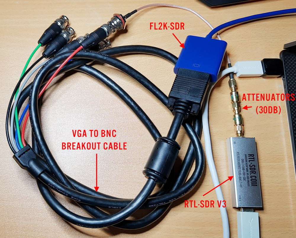
Hardware Used
- The cheapest USB to VGA adapter found on the market. It seems all of the low cost $5 - $15 adapters that indicate "USB 3.0 to VGA", and max resolutions of 1920 x 1080 are compatible as they use the FL2K chip. More expensive units are not compatible. Compatible units all have a similar design (box at the end of a short USB cable, although there are other types too). The brand does not matter. (Amazon) (eBay) (Aliexpress)
- A VGA to BNC breakout cable to connect the FL2K SDR directly to an RTL-SDR (via a BNC to SMA adapter) without illegally transmitting over the air. The Red color breakout is the one connected to the TX pin. (Amazon) (eBay) (Aliexpress)
- A low cost 20dB or more attenuator to avoid overloading the dongle. (Amazon) (eBay) (Aliexpress)
Setup
Note that you must have a USB 3.0 port to use Osmo-FL2K, although a USB 2.0 might work although at significantly reduced bandwidths.
Osmo-FL2K is Linux only at the moment, but it may be possible for someone to compile a Windows version, just like with RTL-SDR. Instructions for downloading and compiling the software are available on the official wiki. It is a standard git clone, cmake, make type procedure which can be done in 2 minutes. You'll also need to probably do an 'sudo apt-get install sox pv' if you want to run the WBFM example.
First we tried to boot into the GNU Radio Live Linux bootable image on a tablet like laptop that only has USB C 3.0 ports. Unfortunately while the FL2K-SDR was recognized, and Osmo-FL2K detected it, there was no signal coming out during test transmissions. It seems that there may be issues when a USB C to USB Type A converter is used.
Next we tried the GNU Radio Live Linux bootable image on a desktop PC and this time Osmo-FL2K worked fine when plugged into a USB 3.0 port. However, plugging it into extended ports seemed to cause it to not be detected. So if you're having trouble getting Osmo-FL2K to work, try other USB 3.0 ports on your PC, and avoid USB C adapters if possible.
We also tried Virtual Box, however the FL2K-SDR wouldn't connect to the Linux guest system, even though USB 3.0 was enabled and the extensions were installed. For VMWare it appears only that the paid versions support USB 3.0.
Testing
WBFM
Following the instructions on the official Osmo-FL2K page we were able to get an WBFM transmission up and running almost instantly. The provided example routes audio from your soundcard into the FL2K-SDR, causing it to transmit WBFM audio at 95 MHz. With this we were easily able to broadcast audio from YouTube to another PC via the FL2K-SDR although there is about two seconds of delay.
To choose the frequency you choose the carrier frequency and the sample rate, and then the transmit frequencies will be the sample rate +/- carrier frequency + harmonics.


Harmonics
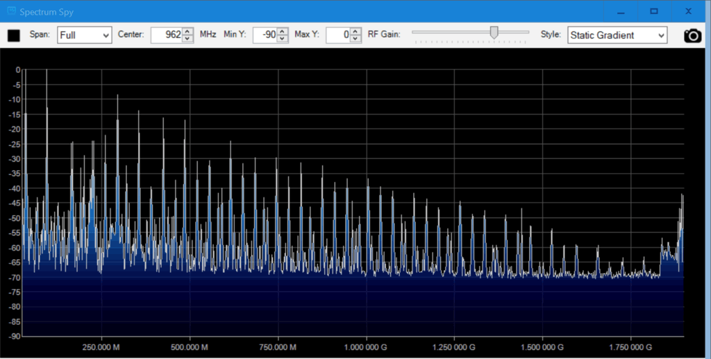
Speaking of the harmonics we had a look at them using an Airspy and the SpectrumSpy software. The image below shows that the harmonics of a signal transmitted at 95 MHz extend all the way up to the maximum range of the Airspy at 1.8 GHz, and probably further. So filtering is very necessary if you ever want to transmit over the air.
Note that when broadcasting at 95 MHz (sample rate 130 MHz, carrier 35 MHz), there is also a strong signal at the carrier frequency. So band pass filtering would be required.
DVB-T
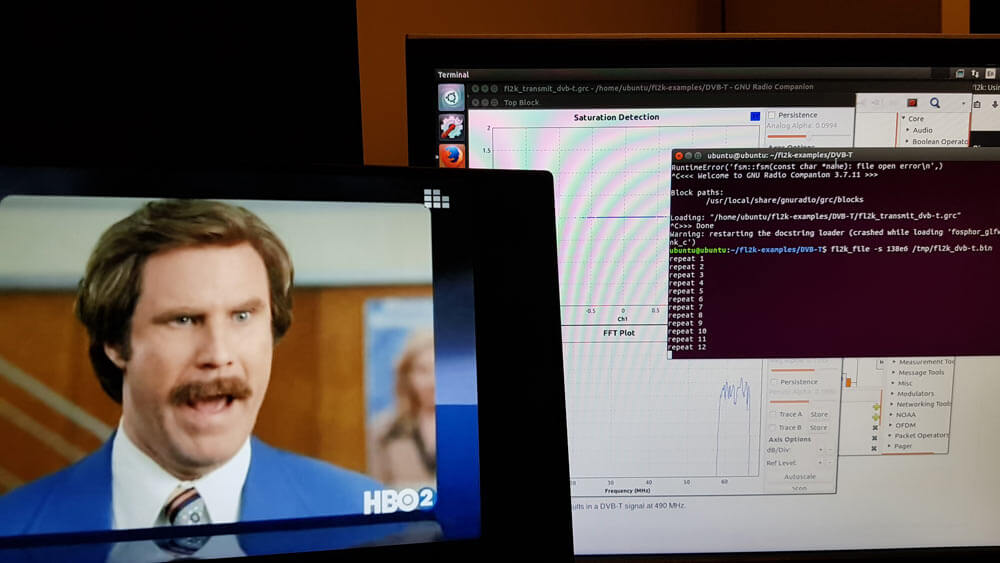
We also tested the DVB-T example found at https://github.com/steve-m/fl2k-examples, which worked flawlessly. By using the connected RTL-SDR dongle with the original DVB-T drivers we were able to receive a transmitted stream at 490 MHz using the ProgDVB software.
To do this follow the instructions in the fl2k-examples/DVB-T readme file to generate samples which Osmo-FL2K can transmit. Then on another PC install the DVB-T drivers for the RTL-SDR, and use ProgDVB to scan 490 MHz by manually editing the multiplexes options.
CPU Usage
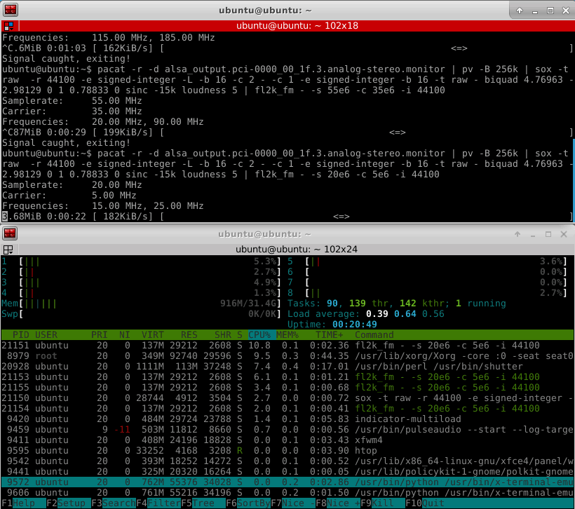
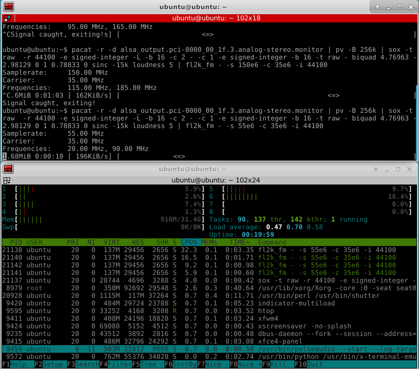
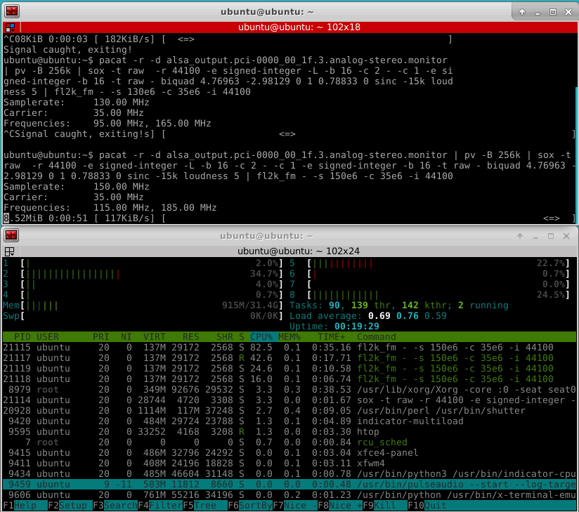
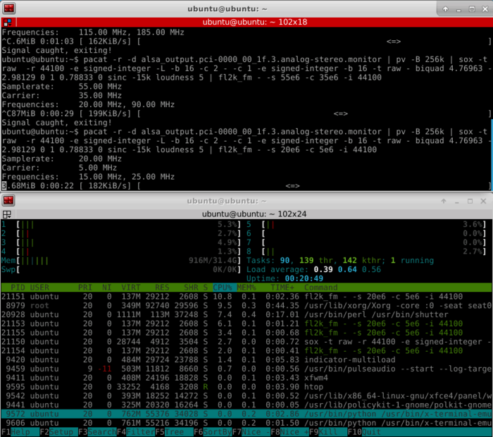
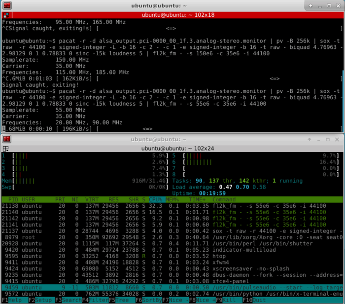
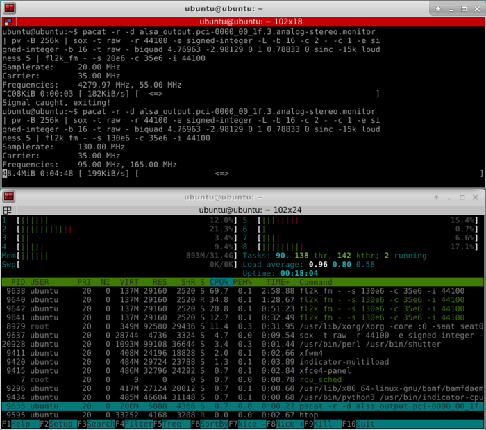
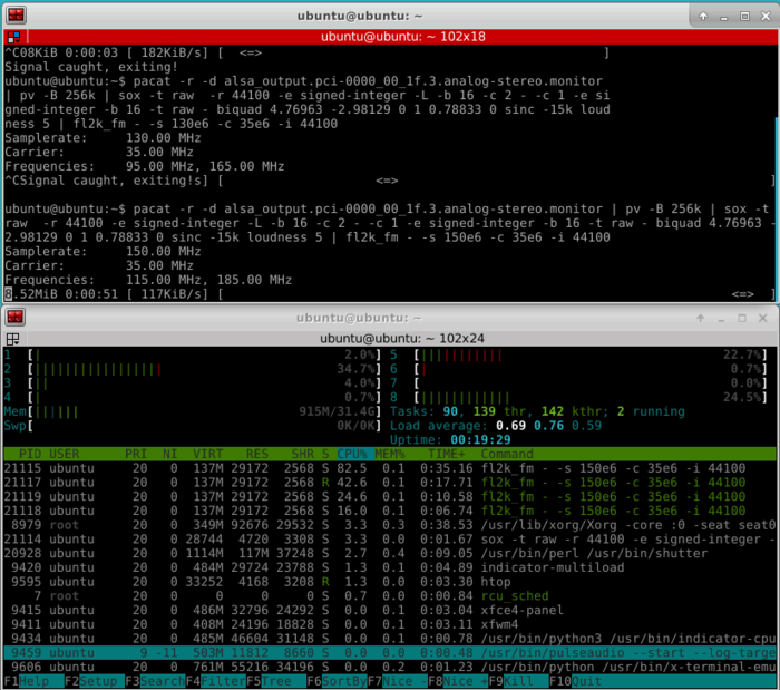
Osmo-FL2K is quite CPU intensive, especially if higher sample rates are used. For this reason it might struggle on singe board computers that support USB 3.0. The images below show some CPU usage examples for sample rates of 20, 55, 130 and 155 MS/S. The test PC uses a fairly powerful i7-6700 CPU.

does anyone have any experience with osmo-fl2k on the new rpi4 with via tech vl805 usb 3.0 controller?
Looking forward for some response on the subject as well, as I wish to buy an rpi4 but I fear whether the usb3 controller is inadequate for high sampling rates.
I’ve tried it and it does not work for me even at reduced sample rates.
Can anyone suggest a SBC with full USB 3.0 that would be capable ?
Mind that a real time kernel would be useful as the test with OdroidXU (exynos5410) have demonstrated.
If the FL2k USB device breaks its stream once, the transmission would not recover. If it does immediately after starting, you will hear just a blip or even nothing at all at the designated frequency.
What sort of problems are you facing?
also setting the linux process priority “nice” value to 20 (highest priority) helps a bit, and switching the power management features adequately (i.e. setting the kernel scheduler to ‘performance’) helps even more.
Mind you that even an i3 laptop with performance options set can have the thread broken if background tasks cause the USB streaming to jitter just once.
Adding self-recovery to the USB device would be a nice addition, for true. But I guess that’s a libusb problem rather than the application’s problem.
Looking at a dongle’s output using fl2k_fm I spotted sideband signals at both sides of the produced carrier at 1.2MHz distance.
It turns out that they occur as power supply noise created by the KB3426 switching mode buck regulators that power both 1.2V and 3.3 V power input lines of the FL2000 chip in several available implementations.
A rather crude mod that includes the removal of the switching mode regulators and their replacement with 2 LM317 (TO220 package) linear regulators cleaned up the mess. And yes I somehow managed to fit them both inside the plastic box, thanks to the miniscule consumption of the chip there are no heat accumulation problems I guess there’s a more elegant way to install linear regulators in there, or someone could be blessed with having an implementation that uses linear reg from the start. In any case, if you open your FL2K case and spot coils in the power section (not the L at the RGB output, visibly spotted coils) expect a (rectifiable if you have mastered a soldering iron) dirty signal.
It is possible to make bts to transmit via fl2k and receive using rtl sdr on 900Mhz ?
Of course. Oczywiście, Jurek 🙂
I cannot get around this error… i installed libusb already.. onyone got the same error message?
CMake Error at CMakeLists.txt:71 (message):
LibUSB 1.0 required to compile libosmo-fl2k
Did you also install the -dev files for libusb ?
hi ben,
The problem consists.. i use linux mint.
When i try to install on lubuntu it works right away.
Dont know why that is.
Hi I have been able to get the WFM to work no problem
Has any one been able to get WSPR on HF to work?
Is it possible for RPi?
No, it isn’t, because you need at least USB3.0 in order to do this. On RPi you could use square wave rpitx (a capacitor and 3-stage LC bandpass filter should be enough before a LNA), or buy a Pine64 or a ODROID XU-4 – two cheapest USB3.0 SBCs.
I wonder… Can we transmit three independent signals by using G and B channels of the VGA as well?
On paper you should be able to, but a computer with enough processioning power to do useful DSP in real time for three antennas will not be cheap. Maybe you could pre-computed everything offline, and streamed the raw bits from a SATA-3 SSD to the USB 3 port. I suppose it depends on what exactly you are trying to do.
It’s pretty impressive the amazing work around to make a cheap tx sdr device!

Just one thing, in the FL2K test hardware image in the article:
The red BNC-ended wire is the antenna pin denoted in the pinout figure:
https://imgur.com/a/C4Yt0aw
Is that correct?
Yes, the colors on the breakout cable match the diagram.
Dose this have the same output power as hackrf?
Nope. This is just a DAC. If you want to have something like HackRF, you should connect it like that: FL2K -> bandpass filter -> RF amplifier -> antenna.
Is there any budget solution for that?
You can build the bandpass with very cheap components: Some ceramic capacitors and some coils made from enamelled copper wire. There are several calculators online where you can get the component values for the specified frequencies.
Low noise amplifiers are on sale for around 5€ on Aliexpress, just select the one that works for your purpose. Antennas can also be build with some wire, there are tons of designs you can find for different frequency ranges. You should also have some coax to connect the things together.
Easy to say but a bit more complex to build. Just the filter calculator will not bring you there. You need some kind of network analyzer to measure and tune the S11. If your S11 is not good your “cheap LNA” may run into oscillations if the design is not unconditionally stable. Another problem is that the “cheap LNA” may produce a lot of IMD products in-band and out-band due to a bad design. Have seen a lot of that in my spectrum analyzer. And the last problem is the antenna. If you can not tune the antenna S11, again your LNA may run into oscillations if the design is not unconditionally stable. So there are many factors if you want to comply with the local regulations. Using a cheap LNA on the RX side is not a big problem, you can spoil just your reception, but using the same cheap LNA on the TX, you may cause a lot of trouble without even knowing that.
Any chance RTL-SDR might re-package and sell these? I know I’d be interested!
-Kenn
Any chance of showing “cpufreq-info” and “htop” to give some indication of how much CPU processing power is required for ~400MB/sec of raw data with a light DSP overhead. And maybe the same with the device connected to a USB 2.0 slot at ~40MB/sec. FM would probably be the at the lightest end of DSP loads and would give a good indication of what the minimum requirements would be.
I added some screenshots at the end of the post showing CPU usage. It is quite CPU intensive especially when higher sample rates are used. The test PC has a relatively fast i7-6700 CPU.
Thank you very much, it gives a better idea of the resources used.
FYI: The reason I asked for “cpufreq-info” is because there can be one a number of different CPU frequency governors active which actually adjust the CPU clock frequency up and down depending on how intensive the workload. Like if the machine is idle the CPU’s could be under clocked all the way down to say 50MHz to use minimal power and under extreme load it can, in the case of a i7-6700, overclock all 4 cores (2 physical x 2 logical) to 4 GHz. I suppose what I am saying is that the CPU load in htop can actually be less at a higher load than a lower load because the frequency of the CPU could have been increased! Which is confusing as hell, but can reduce your power bill.
One way to force htop to show consistent results is to change the governor for the duration of the tests to maximum performance, maximum power usage and maximum fans . e.g.
sudo cpufreq-set -g performance -c 0-3
And then when the tests are finished, set the governor back to something more sensible, or take note of what it was before and return it to that. Any governor where less power is used and the fan is not running constantly.
sudo cpufreq-set -g conservative -c 0-3
A reboot will also reset the governor back to whatever the system default is configured to be.
“cat /sys/devices/system/cpu/cpu0/cpufreq/scaling_available_governors” will usually list the available governors on a given system, and details of most governors can be found here:
https://www.kernel.org/doc/Documentation/cpu-freq/governors.txt
Oh and there is a “powersave” governor which can sometime be handy if running from battery. But like I said it is FYI, I’m not asking you to do anything else.
I think you mean 4 physical and 4 logical cores, (total of 8), also modern desktop systems usually idle at 800mhz, and may or may not be in a sleep state where their power is shut off.
Well, better use LXC instead of full virtualisation. Also, I would rather need a programable band filter (we can use integrated I2C and amplifier solution than a loop-cable test. Even if you don’t have a ham radio operator license, there are many bands you can transmit without a license – CB, ISM, PMR etc.
Licence free means the equipment has to be certified and approved by the regulatory body which is usually the government (unless you are military this applies to you). You cannot DIY a transmitter on CB, ISM, PMR and transmit it in the air legally without getting the equipment approved by the government, even they do not need you to have a persona licence.
Amateur radio equipment does not require regulatory approval if you have the advanced level of licensing for you to use, such as DIY equipment.
There are very low power exemption for this of course and it depends on which country you reside in. But CB, ISM, PMR are not one of those “very low power” assigned spectrum.
Typo “Note that when broadcasting at 95 MHz (sample rate 100 MHz, carrier 35 MHz)” should read “Note that when broadcasting at 95 MHz (sample rate 130 MHz, carrier 35 MHz)”.
Thanks, fixed the typo.
It’s incredibly impressive what dedicated people can do. The total price would be comparable to RPi though (and you can run stuff right on RPi, no need for another computer).
My understanding (also) is that for RPiTX you will primarily need a low pass filter rather than a bandpass filter (an LPF is slightly easier to make).
Please correct me if I am wrong; never actually used RPITX.
I haven’t used the RPi transmit capability either, so I don’t know what it’s maximum fundamental frequency is. But if you’re going to rely on a harmonic of the fundamental (for example, using the third harmonic of a 33.33 MHz signal to transmit at 100 MHz) you’re going to want to use a bandpass filter.
If the Pi’s output signal is already on the desired frequency, then you can get by with a lowpass filter.