Saveitforparts: Testing a Prototype of the NanoFarfield Portable Antenna Measurement System
Back in March, we posted about the upcoming crowdfunding campaign for the NanoFarfield antenna far-field measurement system.
NanoFarfield is a kit comprising a NanoVNA, custom measurement software, two tripods, a transmit antenna, and an Azimuth-rotating platform for the receive antenna. The idea is to enable low-cost antenna radiation pattern measurements by leveraging the low multipath characteristics of a wide-open field. This is much cheaper than hiring an anechoic chamber.
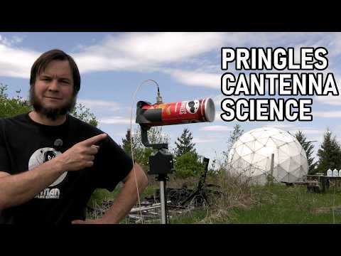
Over on YouTube, Gabe from the saveifforparts channel has received an early prototype and put up a video of his tests. In the video, Gabe unboxes the unit, shows all the parts, and then sets it up in a field to test the included antennas, as well as a homebrew Pringles Wi-Fi cantenna.
Overall, he notes that the system worked well, producing the expected radiation plots. There were some downsides noted, such as the cheap tripods not being stable enough and falling over in the wind, and that the manual and software may still need a little work.