Category: Antennas

Measuring Antenna Gain Patterns with Discovery Drive

Our Discovery Drive campaign is currently being crowd-funded on Crowd Supply. Please consider ordering a unit if you are interested in a high-quality, low-power, and portable antenna rotator. Below is an update from the campaign exploring a potential use-case for measuring antenna gain patterns:


In this update, we’ll examine an alternative use case: measuring antenna gain radiation patterns.

One interesting use of a capable Az/El rotator is to measure the radiation pattern of various antennas. This is normally done in an anechoic chamber, but if you have a large enough open space, it can be done cheaply with a rotator and signal source.

To test this as a proof of concept, we used Claude code to very quickly create a tool that could help us create an antenna pattern plot. The software tool simply rotates the antenna on the Discovery Drive one step at a time, measures the SNR using an RTL-SDR, and plots the reading on a graph. To be clear, this simple setup is not providing any sort of calibrated readings, but it will at least give you an idea of what the radiation pattern and performance of an antenna looks like.

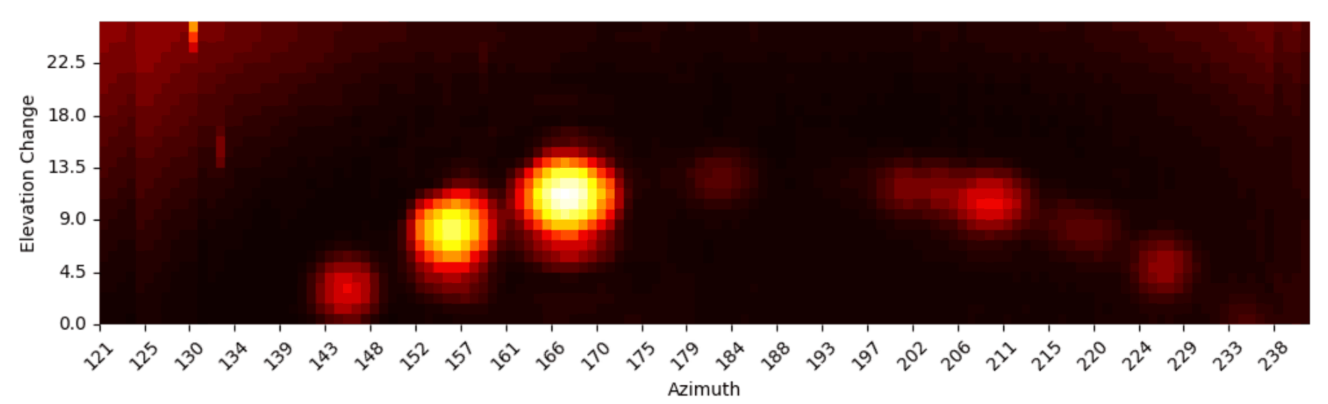
In our test, we mounted a TV Yagi on the Discovery Drive and used our software to plot the radiation pattern at 433 MHz. As expected from a Yagi, we see higher gain at the front and lower gain at the rear.

Antenna Gain Results

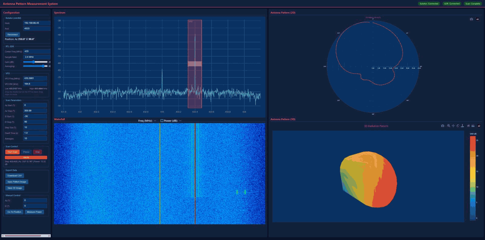
Due to a lack of a suitable open area, this test was performed in a small backyard and, hence, the radiation pattern is a little lopsided due to multipath. In this test, we also used a simple omnidirectional antenna for the signal source, which exacerbated the multipath. A way to improve this test would be to use a directional antenna on the transmit side, too.

We will release this open-source tool for others to play with, but please be aware that it was only created for proof of concept. However, if there is interest, we can continue to refine it.

Below is a photo of the physical setup. A HackRF with Portapack and whip antenna are mounted on a tripod a few meters away, while the Discovery Drive carries a Yagi antenna. As the Discovery Drive rotates the Yagi through 0 to 360° in azimuth and -30 to 90° in elevation, it measures the received power at each step.

Antenna Gain Measurement Backyard Setup

Discovery Drive Campaign Now Live!

We're extremely pleased to announce that our campaign for our Discovery Drive automatic antenna rotator is now live on Crowd Supply! Pricing is reduced during the campaign period, so check it out soon!

Discovery Drive is an automatic antenna rotator designed for use with our Discovery Dish product, as well as similarly sized antennas such as Wi-Fi grid and Yagi antennas.

A motorized rotator, such as Discovery Drive, enables precise tracking of fast-moving polar orbiting satellites using a satellite dish or directional antenna. Examples of polar orbiting weather satellites include METEOR-M2, METOP, and FENGYUN. Depending on your location, you may also have access to other interesting satellites that dump data over specific regions.

In addition to public weather data, operators and enthusiasts might be interested in using Discovery Drive to track CubeSats, and amateur radio operators may wish to track amateur radio satellites.

Amateur radio astronomy hobbyists can map the galaxy in the hydrogen line spectrum using Stellarium, or custom software to aim a Discovery Dish with H-Line feed, allowing you to scan multiple parts of the sky in one night.

Discovery Drive - A Motorized Antenna Rotator Engineered for Discovery Dish

NanoFarfield: A Portable Far-Field Antenna Measurement Platform (Coming Soon to Crowdfunding)

Thank you to Antenom Antenna Technologies for submitting news about the upcoming crowdfunding campaign for their "NanoFarfield" antenna far field measurement system.

When building and measuring antennas, most people stop at measuring VSWR. However, VSWR is only a small part of the picture for antenna performance. The antenna's far-field pattern determines its gain in a particular direction. Measuring this is typically difficult as it requires a signal source, hiring and travelling to an expensive anechoic chamber, and some sort of automated system to rotate the antenna 360 degrees.

In recent posts, we've seen low-cost DIY solutions explored that use a NanoVNA or RTL-SDR to measure an antenna in an open field (to avoid multipath reflections like an anechoic chamber would) at various points, and then charting the results. However, this is a slow, manual process and requires purchasing and setting up various individual components.

NanoFarfield productizes the low-cost approach, providing a portable measurement system that can be brought into an open environment. The measurement process is automated, by using a motorized rotator which spins the antenna under test 360 degrees in front of a directional signal source. The team write:

As many SDR users know, building antennas is relatively easy, but measuring the actual radiation pattern is often difficult. Normally this requires an anechoic chamber or a large outdoor antenna range, which is usually inaccessible to hobbyists, students, and small labs.

We have been working on a portable antenna measurement system called NanoFarField, designed to measure antenna radiation patterns outside the lab using commonly available VNAs such as NanoVNA or LiteVNA.

Instead of requiring a full antenna range facility, the system allows users to perform radiation pattern measurements in open environments using a compact rotating platform and VNA-based S21 measurements. The goal is to make antenna pattern measurement accessible to:

• SDR and ham radio experimenters
• antenna designers and RF engineers
• universities and student labs
• field testing scenarios

The system effectively acts as a portable antenna range that can fit into a backpack.

Typical workflow:

The antenna under test is placed on the rotating platform.

A reference antenna is positioned at a fixed distance.

The NanoVNA / LiteVNA performs S21 measurements while the antenna rotates.

Software reconstructs the radiation pattern from the measurement data.

This allows users to measure:

• azimuth radiation patterns
• antenna directivity trends
• relative gain patterns
• beamwidth and nulls

without requiring an expensive measurement facility.

Because many SDR enthusiasts design and build their own antennas, we thought this tool could be useful for the community as a low-cost method to visualize antenna performance.

The frequency range is specified at 50 - 6000 MHz, with a typical angular resolution of 1 degrees, and it includes a wideband amplifier to improve results. The hardware is provided as open source, however, the software will be closed source, and provided as a Windows executable. 

NanoFarfield: Low-Cost Antenna Radiation Pattern Measurement System (50–6000 MHz)

Discovery Dish 1420 MHz Hydrogen Line Feed Tested with a WiFi Grid Dish

Thank you to Alex P for writing in and sharing with us his detailed evaluation of the Discovery Dish 1420 MHz hydrogen line feed when paired with a low-cost 1m WiFi grid dish. The goal was to see how well this near off-the-shelf setup performs as a hydrogen line radio telescope. The Discovery Dish feed integrates the dipole very close to the internal LNA and filters to minimize losses, uses a weather-sealed enclosure, and is built around a low-noise Qorvo QPL9547 amplifier, which has a very low noise figure at 1420 MHz.

Alex used 4NEC2 with a simple geometry approximation to analyze the beam pattern and also experimentally determined the optimal feed-to-dish spacing for the WiFi grid. The results show that the Discovery Dish feed significantly outperformed a more standard feed + external LNA setup.

Alex also shows how he uses aluminum foil, or conductive foam, to shield the feed from all signals during a background correction scan. Generally, for background correction scans, we recommend pointing towards a cold area of the sky (any area far away from the Milky Way with little to no hydrogen), but Alex prefers this method.

Discovery Dish 1420 MHz Hydrogen Line Feed Tested on a WiFi Grid Dish

Eavesdropping on Sensitive Data via Unencrypted Geostationary Satellites

Recently, Wired.com released an article based on research by researchers at UC San Diego and the University of Maryland, highlighting how much sensitive unencrypted data many geostationary satellites are broadcasting in the clear.

The researchers used a simple off-the-shelf 100cm Ku-band satellite dish and a TBS-5927 DVB-S/S2 USB Tuner Card as the core hardware, noting that the total hardware cost was about $800. 

Simple COTS hardware used to snoop on unencrypted satellite communications.

After receiving data from various satellites, they found that a lot of the data being sent was unencrypted, and they were able to obtain sensitive data such as plaintext SMS and voice call contents from T-Mobile cellular backhaul and user internet traffic. The researchers notified T-Mobile about the vulnerability, and to their credit, turned on encryption quickly.

They were similarly able to observe uncrypted data from various other companies and organizations, too, including the US Military, the Mexican Government and Military, Walmart-Mexico, a Mexican financial institution, a Mexican bank, a Mexican electricity utility, other utilities, maritime vessels, and offshore oil and gas platforms. They were also able to snoop on users' in-flight WiFi data.

Cellular Backhaul
We observed unencrypted cellular backhaul data sent from the core network of multiple telecom providers and destined for specific cell towers in remote areas. This traffic included unencrypted calls, SMS, end user Internet traffic, hardware IDs (e.g. IMSI), and cellular communication encryption keys.

Military and Government
We observed unencrypted VoIP and internet traffic and encrypted internal communications from ships, unencrypted traffic for military systems with detailed tracking data for coastal vessel surveillance, and operations of a police force.

In‑flight Wi‑Fi
We observed unprotected passenger Internet traffic destined for in-flight Wi-Fi users on airplanes. Visible traffic included passenger web browsing (DNS lookups and HTTPS traffic), encrypted pilot flight‑information systems, and in‑flight entertainment.

VoIP
Multiple VoIP providers were using unencrypted satellite backhaul, exposing unencrypted call audio and metadata from end users.

Internal Commercial Networks
Retail, financial, and banking companies all used unencrypted satellite communications for their internal networks. We observed unencrypted login credentials, corporate emails, inventory records, and ATM networking information.

Critical Infrastructure
Power utility companies and oil and gas pipelines used GEO satellite links to support remotely operated SCADA infrastructure and power grid repair tickets.

The technical paper goes in depth into how they set up their hardware, what services and organizations they were able to eavesdrop on, and how they decoded the signals. The team notes that they have notified affected parties, and most have now implemented encryption. However, it seems that several services are still broadcasting in the clear.

A Small 11.2 GHz Motorized Radio Telescope with TV Dish and RTL-SDR

Thank you to Kaustav Bhattacharjee for writing in and submitting to us his project, where he created a small 11.2 GHz motorized radio telescope with a TV dish and an RTL-SDR. A full description of Kaustav's work can be found in a white paper he wrote on behalf of the Department of Physics at the Indian Institute of Technology Roorkee. In summary he writes:

Briefly put, the hardware Setup comprises a 66 cm parabolic dish, a standard Ku-band LNB with bias tee power injection as the frontend, an RTL-SDR V3 tuned to 1.45 GHz (due to downconversion) as the receiver and a Raspberry Pi 5 handling SDR data (via GNU radio) and stepper motor control (using GPIO pins). A heatmap of the southern sky at 0.9° resolution, showing a belt of geostationary satellites, is the primary result of interest!

We also want to point out that his rotor setup involves several 3D printed gears driven by two NEMA17 stepper motors. However, Kaustav notes that the long term resolution is limited due to cumulative backlash errors from the open-loop control scheme.

Kaustav's 11.2 GHz RTL-SDR Radio Telescope
Geostationary satellites visualized with the radio telescope

A Video on Optimizing VLF Loop Antennas

VLF (Very Low Frequency) refers to signals in the 3–30 kHz range. Software-defined radios like the SDRplay RSPdx can pick up these signals with an appropriate antenna.

Over on YouTube, @electronics.unmessed has uploaded a video showing how you can build a high-performing VLF loop using a single loop of wire and a balun. The one-turn design results in a naturally low impedance at low frequencies. A balun is then added to step up the impedance, resulting in impedance compatibility with an SDR.

The video explains the concepts behind VLF loops using an equivalent circuit model and shows how conductor thickness offers little benefit above 10 kHz (though wide sheet conductors can add ~3 dB), larger loops scale with area but 2 m is a good indoor compromise, extra turns help small loops but underperform a single turn with a proper transformer, and alternative ferrite mixes give little improvement over standard choke cores. Ultimately, it is concluded that a one-turn loop with a well-chosen balun is one of the most effective designs.

If you're interested in similar content, there are also several other interesting videos on the @electronics.unmessed channel about VLF antennas, mag loop antennas, SDR reception, and more.

VLF Loop - What really Matters? (EP172)

Decoding ADS-C with a Cheap Aliexpress LNB and SDRplay RSP1B

Thank you to Nagy István for sharing with us his setup for decoding ADS-C with a 180cm prime focus dish, a cheap Aliexpress LNB, an Aliexpress bias tee, and an SDRplay RSP1B.

István receives the ADS-C signal from the Inmarsat 4A-F4 satellite, which he can see from his home in Hungary. 

István also notes the following information about the Chinese LNB:

This LNB original for DVB reception, but it works on Inmarsat reception, 3.6Ghz where ADS-C signals are, without any modification... But sometimes you need correcting frequency because of LNB oscillator drifting. I don't use dielectric plate, I don't have any material for this, at the moment.

Compared to ADS-B, which continuously broadcasts an aircraft’s GPS position and velocity to any ground station or nearby aircraft, ADS-C instead sends position reports via satellite, and is especially used over oceans and remote areas without ADS-B ground receivers.

However, ADS-C is relatively complex for hobbyists to receive due to the need for a large satellite dish and LNB to convert the 3.6 GHz frequency down to a frequency receivable by most SDRs. However, fortunately, as István shows, the LNB can be obtained cheaply these days.

Inmarsat ADS-C decoding with Jaero and Virtual Radar

ADS-C Being Received with an 1.8m dish, cheap Aliexpress LNB and SDRplay RSP1B.