Tagged: VLF

Testing the YouLoop on VLF & LF Reception with an Airspy HF+ Discovery

Over on his YouTube channel Frugal Radio has been testing his YouLoop passive magnetic loop antenna on VLF and LF reception with his Airspy HF+ Discovery. In the video Frugal Radio browses the VLF & LF spectrum, making note of some interesting signals, and showing how well the combo receives.

The YouLoop is a low cost passive loop antenna for HF and VHF. It is based on the Möbius loop design which results in a high degree of noise cancelling. However the main drawback is that it is a non-resonant design, which means that it needs to be used with ultra low MDS receivers like the Airspy HF+ Discovery. We have YouLoop stock available in our shop for $34.95 with free worldwide shipping.

Airpsy YouLoop passive antenna review on VLF & LF with an HF+ Discovery and SDR# during storms!

Building an Underground Earth Probe Antenna for 0 – 14 MHz TX/RX

Thank you to Jean-Marie Polard (F5VLB) for letting us know about his work in creating underground "earth probe" antennas that work for both RX and TX between 0 - 14 MHz, and are especially good at VLF and below. He writes:

Can't install an antenna at home? Madame refuses the masts, taut son? One solution, The Earth probes antenna.

Our group (https://www.facebook.com/groups/earthprobes/) started in January 2019. At first everyone made fun of me, the professionals called me crazy and today with more than seven hundred members, we installed underground antenna systems and the results are there.

Between 0 and 14MHz, in transmission and reception, it works!

This system dates from 1914/1918 but has been brought up to date.

It doesn't take much to get started, just the urge to try.

Mad of vlf - elf - ulf ? come here https://www.facebook.com/groups/VLF.ULF.ELF/ nearly 1000 members are waiting for you.

So when? Welcome everyone.

To access the Earth Probes and VLF.ULF.ELF groups you'll need a Facebook account. The groups contain a number of research papers documenting the concept, and the photos section. From the photos, an earth probe antenna appears to consist of two long grounding rods spread over a distance, or a grounding rod and long buried wire, combined with a balun.

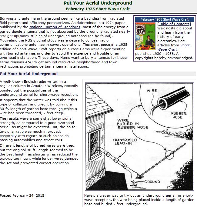
An example of an underground antenna setup from a 1935 shortwave magazine.

Using a Raspberry Pi 3, USB Soundcard, Speclab and Exagear to Detect SAQ VLF Transmissions

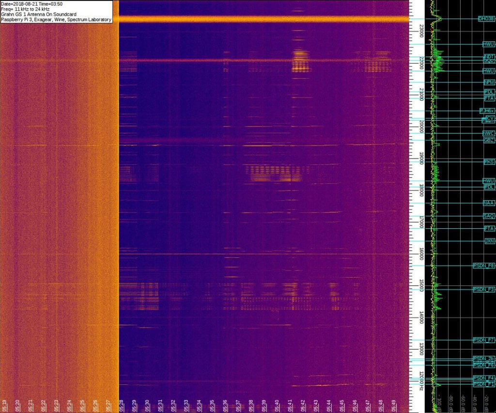
Thanks to DE8MSH for writing in about his project that involves using a Raspberry Pi 3 and cheap 7€ USB sound card connected to an old Grahn GS1 VLF antenna to detect the SAQ VLF station. Standard PC or USB sound cards can be used as a narrowband VLF capable SDR simply by connecting an antenna to the sound inputs. SAQ (aka Grimeton Radio Station) is a heritage VLF transmitter in Sweden that transmits CW at 17.2 kHz, normally only on Alexanderson Day and Christmas Day, but can sometimes unofficially transmit without announcement due to maintenance, training or local events.

In terms of software running on the Pi 3 DE8MSH uses Spectrum Laboratory (speclab) to monitor the sound card waterfall, and has written a Python script that uploads the processed images from speclab to a Twitter account every 20 minutes. This way he hopes to be able to detect any unannounced SAQ transmissions from his station in Sweden. 

Spectrum Laboratory is actually a Windows and x86 only program, however as shown in one of our previous posts, it is possible to use a special compatibility emulator called Exagear which allows you to run x86 programs on ARM hardware. Together with Wine you can then run x86 Windows programs on single board computers like the Raspberry Pi 3 which run Linux on ARM hardware.

Speclab Screenshot from DE8MSHs Pi3 soundcard monitoring system

Comparing the RSP1 and RSP2 on VLF, LF and AM BC Reception

Over on YouTube user Mile Kokotov has uploaded two new videos that show both the SDRplay RSP1 and RSP2 receiving VLF, LF and AM BC signals. The SDRplay RSP1 is a 12-bit SDR that can receive from about 10 kHz – 2 GHz. Recently the RSP2 was released which is an upgrade over the RSP1 with additional filters and features. On this blog we did an initial review of the RSP2 and found mostly improved performance over the RSP1.

Mile writes about the signals he receives:

Antenna on RSP2 is connected to its Hi-Z port.

Here are some information about signals in this video:

60 kHz Time signal from NPL is a radio signal broadcast from the Anthorn Radio Station near Anthorn, UK.
The signal, also known as the MSF signal is broadcast at a highly accurate frequency of 60 kHz and can be received throughout the UK, and in much of northern and western Europe. (But I am receiving it in Macedonia) The signal’s carrier frequency is maintained at 60 kHz controlled by caesium atomic clocks at the radio station.

77.5 kHz Time signal is German DCF77 longwave time signal and standard-frequency radio station. The highly accurate 77.5 kHz carrier signal is generated from local atomic clocks that are linked with the German master clocks.

On 295 kHz there is NDB (Non directional Beacon) from Alexander The Great Airport near Skopje (about 80 km from my home)

On AM Broadcast Band (530 kHz – 1620 kHz) you can see how many AM stations are on the spectrum display (with 9 kHz raster) receiving here at my home with Mini-Whip antenna which is only 10 cm long!

More information you can find on my web-page: http://www.qsl.net/z33t

The first video shows reception with a Mini-Whip, and the second with a Delta Loop. We don’t see much difference in reception between the RSP1 and RSP2 in these videos but viewers with more sensitive ears may be able to tell us if they notice any differences.

SDRplay RSP1 and RSP2 receiving VLF LF and AM BC with Mini-Whip

SDRplay RSP1 and RSP2 receiving 60 kHz and 77.5 kHz Time signals in Macedonia

Receiving the SAQ VLF Signal with an Airspy + Spyverter and SDRplay RSP

Over on YouTube user Mile Kokotov has uploaded a video showing his reception of the SAQ very low frequency (VLF) signal. The SAQ transmitter is based in Grimeton, Sweden and transmits at 17.2 kHz, which is well below the frequency of most radio communications. SAQ only transmits its beacon on certain days, and last Sunday July 3rd 2016 the SAQ beacon activated to celebrate Alexanderson day, which is named after Swedish radio pioneer Ernst Frederick Werner Alexanderson.

In the video both the Airspy + Spyverter and the SDRplay RSP appear to receive the SAQ VLF signal equally well. In the video description Mile writes:

“SAQ”- Radio Station at Grimeton is a VLF transmission facility at Grimeton, Sweden. It has the only working Alexanderson alternator rotating armature radio transmitter in the world and is classified as a World Heritage Site.

The transmitter was built in 1922 to 1924 to operate at 17.2 kHz. The antenna is a 1.9 km wire aerial consisting of eight horizontal wires suspended on six 127-metre high freestanding steel pylons in a line, that function as a capacitive top-load to feed energy to six grounded vertical wire radiating elements.

Until the 1950s, the Grimeton VLF transmitter was used for transatlantic radio telegraphy to Radio Central in Long Island, New York, USA. From the 1960s until 1996 it transmitted orders to submarines in the Swedish Navy.

The Alexanderson transmitter became obsolete in 1996 and went out of service. However, because it was still in good condition it was declared a national monument and can be visited during the summer.

On July 2, 2004, the Grimeton VLF transmitter was declared a World Cultural Heritage site by UNESCO. It continues to be used on special occasions such as Alexanderson Day to transmit Morse messages on 17.2 kHz. Its call sign is SAQ.

Recent transmissions from SAQ on 17.2 kHz with Alexaderson 200 kW alternator, was on Alexanderson day (Sunday, July 3rd 2016) at 09:00 UTC.

Distance between SAQ transmitter in Grimeton, Sweeden and Macedonia where the signal was received is about 1850 km.

Receiving with:
1. AIRSPY R2 – SDR + Spyverter and SDRsharp software.
2. SDRplay RSP1 and SDRuno software.

Both SDR receivers settings were previously set for maximum S/N ratio.

Antenna is Mini-Whip 10cm homemade active antenna on 6.5 meter plastic pole.

The LPF filter (fc=535 kHz) is used also.
SAQ VLF Receiving with Airspy+Spyverter and SDRplay

Optimizing Reception of VLF frequencies on an RTL-SDR Dongle

Over on his web site, Martin (G8JNJ) has uploaded a new article discussing how to optimize reception of VLF (<10 kHz) signals on a direct sampling modified RTL-SDR. He writes that the main problem with the RTL-SDR receiving VLF frequencies is that there is significant overloading caused by broadcast stations operating on the LF and MF bands.

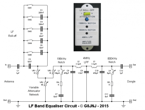
So in order to optimize VLF reception, Martin built an external frequency equalisation network which has the following components and functions:

  • 2MHz Low pass Filter – to minimise alias signals originating at 30MHz
  • 20dB Variable attenuator – to set the overall signal level fed into the dongle
  • Switched LF roll-off – to optimise the performance at frequencies around 10KHz in the presence of strong lightning surges
  • -10dB notch at 198KHz – to reduce level of BBC R4 broadcast station in the LF band
  • -10dB notch at 800KHz – to reduce level of local broadcast stations in the MF band

His screenshot results show that his filters work well and significantly reduce the effect of lightning pulse noise at 9 kHz. With the filters in place and properly optimized with the attenuator and various switches, he is able to receive Russian Alpha navigation signals at frequencies around 12 and 14 kHz and the 300 to 500 kHz aeronautical and maritime navigation bands.

G8JNJ's LF Band Equalizer Circuit
G8JNJ’s LF Band Equalizer Circuit

Comparing the Ham-It-Up Upconverter with the SV1AFN Upconverter

Over on YouTube user Mile Kokotov has uploaded a video showing a comparison between the ham-it-up and SV1AFN upconverters. An upconverter allows reception of VLF to HF signals with SDR dongles such as the Airpsy and RTL-SDR.

Mile shows that both the ham-it-up and SV1AFN upconverters use the same core component, a double balanced mixer ADE-1. However, the ham-it-up comes with the option for a noise circuit to be populated. A noise circuit is useful if you want to measure the response of a filter or antenna for example. With the ham-it-up the noise source components are sold seperately and need to be carefully soldered on.

On the other hand the SV1AFN upconverter comes with a built in selectable LNA and better filtering circuitry. The SV1AFN upconverter also uses the ADE-1 in a slightly different design compared to the ham-it-up which allows for much improved performance at VLF frequencies.

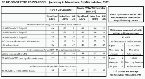
In the results Mile uses his Airspy and shows that the SV1AFN upconverter is significantly better at receiving VLF frequencies, and also better at receiving a 28.205 MHz beacon. The results are summarized in the table captured from the video shown in the image below. In the second video Mile also compares the local oscillator drift of each upconverter.

Upconverter comparison results.
Upconverter comparison results screencap.
RF Upconverters Comparison: Ham it Up vs SV1AFN - part1

Receiving VLF with a PC sound card, Miniwhip Antenna and SAQrx

Over on YouTube user Mile Kokotov has uploaded a video showing how he is able to receive Very Low Frequency (VLF) signals between 300 Hz to 30 kHz using just his PC, a Miniwhip antenna connected to his sound card input port and a program called SAQrx Panoramic VLF Receiver. This allows reception of signals between 0-48 kHz with a sound card that can sample at 96 kHz.

Using this set up he is able to receive the Alpha navigation system beacons which are at around 10-12 kHz and some other Navy navigation system beacons between 18 and 48 kHz from his home in Macedonia.

Receiving VLF with PC and software only