An R820T2 Breakout Board
The R820T2 is the tuner chip used on most RTL-SDR dongles. It is also used on the Airspy, a more advanced higher end SDR. All in all, it is a very good tuner chip, but it is mostly limited by the low-bit ADC on the RTL2832U chip in the RTL-SDR.
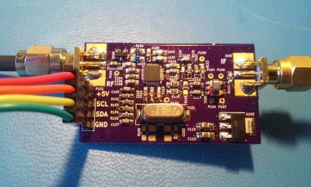
We’ve just been informed that there is now a custom DIY breakout board available for the R820T chip which is made by Eric Brombaugh who is an SDR experimenter. This is great for those wishing to do home brew SDR experiments with the R820T2 chip, for example you could perhaps implement your own SDR with a higher end ADC chip on a development boards.
The breakout board is essentially the exact implementation which is shown in the R820T datasheet. It is available as a 4-layer PCB on Osh Park and it “provides a simple 4-pin interface with power, ground and I2C bus for controlling the tuner. A broad-band RF input and 10MHz IF output are provided on SMA connectors.” Eric has also provided us with a simplified driver based on the Airspy and Linux media driver code which allows you to control the R820T2 from an STM32F0xx processor.


I recently saw a talk on youtube regarding using an FPGA prototyping setup to create a high bandwidth receiver – the technical depth of the talk along with available documentation and example code puts the project within my capabilities from a coding standpoint but I had a lot to learn in terms of electronics and circuit design before I could attempt anything.
However I can reliably populate surface mount boards as I have a primitive reworking station with a hot air gun and plenty of practice – this board will remove a great deal of complexity for me – I’ve found some similar development boards for various ADCs, even ones that are RF specific 50ohm designs – with a capable FPGA development board maybe, just maybe – I can reach the stage where it’s just a matter of software/FPGA design.
My thanks to Eric Brombaugh for making me lose lots of sleep in the near future 🙂
Glad to hear that’s helpful. Do take a look around the rest of my site – I’ve got open-source designs for a variety of FPGA-based SDR systems posted. Probably the most complete is my iceRadio project which includes both the FPGA and ARM code for a complete 0-20MHz receiver with various modulations as well as source materials for all the boards.
iceRadio
It’s very difficult to find ADCs with high resolution, wide bandwidth and low cost. 24-bits is pretty much unobtainium. I’ve got a 14-bit 80MSPS board that I’ve been testing lately – works great with the R820T2 breakout described above: is the link – but be aware that the chip costs almost $70 in small qty.
Someday when we have flying cars and universal translators, wideband 24bit adc’s will be a dime a dozen. We’ll listen to them tuned to various and sundry signals as our pet velociraptor, recently cloned, curls up at our feet.
I think you’d want a 20 MHz ADC…
I wonder if there’s a cheap 24bit dac that will go to 10MHz?
24-bit with 10MHz bandwidth means that nearly 8 bit could end up sampling the Johnson Nyquist noise from the resistors within the circuit. For 10MHz of bandwidth 17-bits or less would be more appropriate, at room temperature, in most designs, at least to avoid pouring the power budged down the drain sampling random noise. Unless of course you were trying to deliberately design a random number generator, in which case you would throw away the top 16 bits and focus on the noise.
I miss read DAC, as ADC, but the same general idea would probably also apply.