Receiving Iridium Satellites with a HackRF Portapack and Cheap Antenna
Recently Jared Boone, creator of the HackRF portapack posted on his blog about his experience with trying to receive Iridium satellite signals. The HackRF is 8-bit, ~0 – 6 GHz, RX/TX capable SDR, and the Portapack is a kit that allows the HackRF to go portable, by adding an LCD screen, battery pack and control wheel. Iridium is an L-band satellite service that provides products such as satellite phones and pagers. Back in December 2014 we posted how it was found that Iridium pager messages could be decoded.
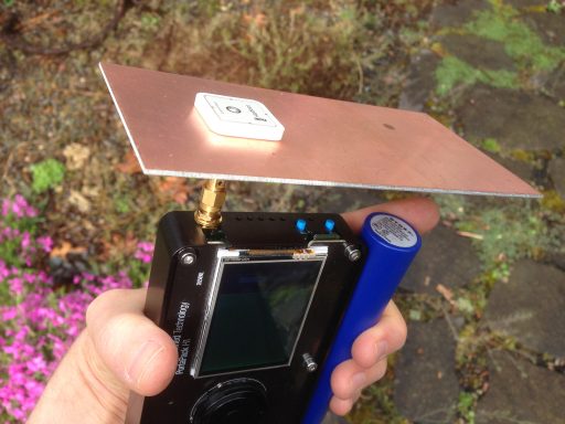
To receive Iridium Jared used a simple ceramic patch antenna mounted on a piece of cheap copper clad fibreglass. This simple antenna was good enough to receive the Iridium signals with good strength. With this set up Jared was able to easily go outside and receive some packets and record them. He writes his next steps are to try and run the Iridium pager decoder on them and see what packets he captured.


AD5NL… Many thanks for your suggestions on the lindenblad antenna, I searched google and I spotted some interesting designs, I’ll definitely try one sometime.
Adam… Thanks also for your very interesting video, the helix antenna looks quite simple but very effective… that’s what I like :). I need to keep my eye out for a large suitable can. Also, any idea when we might get our hands on the Mix4All ?
Sorry, was for 5.8 GHz, not 2.4, but the same basic principle applies. You’d just need beefier booms for the parasitic elements (which would be about 4 inches long at 1.6GHz).
http://fpvlab.com/forums/showthread.php?7183-A-high-gain-CP-OMNI-finally!-Parasitic-Lindenblad
Sorry for the bad threading. This was a follow-up to my reply to Terry Gaff below (under “Designing on a juicy cup” thread about antennas).
It looks like mission impossible using the presented HW.
The antenna mod is completely wrong. Do not apply that approach.
What u suggest?
I suggest not to use the presented HW antenna modification used. It makes things worst than already weak performance GPS antenna.
So what exactly would you suggest other than “not this”?
Hey, Adam. 9A4QAV, right? I’ve built your 7-inch patch antenna and I love its performance with the SDRplay. I would recommend it to anyone trying to receive Iridium. This project will mean we can have “phones” that receive all traffic, and that is amazing. Can’t wait ’til it’s perfected.
Yep, that’s me 🙂
I check quickly your blog and I am surprised that your helix antenna design went wrong and without success. You should have much stronger signal using the Helix antenna comparing to my patch design. Of course, considering the fact that you did not make some basic mistakes, quite possible as more than 50% helix design are wrong on the web. Otrher than that, the helix antenna is quite wideband and delivering descent directivity. If you compare the value for the money, this should be the winner. OK, even my patch antenna is not expensive but helix can deliver some 5-6dB more gain and this is not a small value.
SDRPlay is a nice device, running the gain to max with the patch antenna will give you a lot of fun. Adding some low I.L. bandpass filter would make this system really nice.
The ceramic patch antenna described in this article is a bad performer. just on the edge for the iridium but using the high performance receiver and not deaf HackRF without LNA. Poor performance GPS patch antenna was even more spoiled by adding the “big reflector”. First, the SMA connector was not soldered properly and the antenna has no reflector (ground). Second, there is a big mismatch, the way the SMA is soldered and the most important fact is that adding big reflector does not add gain in this case. Such a big reflector spoil the axial ratio. Axial ratio is one of the most important aspect of the circular polarization antenna. If you spoil the axial ratio you may end up with almost linear polarization. Linear vs circular polarization is resulting -3dB in the signal. At the end, the ceramic patch that should deliver 3dB gain circular will end up with 0dB circular gain.
Forgot to mention, the extra losses are introduced also by offset patch position over the big reflector.
This is a perfect example of how antenna should not be designed 🙂
I appreciate your experience in this area. Would it be possible to continue this on IRC?
Please continue discussion on here so we can all learn.
I’d really like to try building a helical, bifilar and Quadrifilar type antennas for Iridium… anybody got any good info, I’m sorta stuck on how the second two should be fed to the connector.
Terry — might be reasonably easy to build a parasitic Lindenblad using some coax and maybe some scrap plastic and wire for the parasitic elements. Basically, with a parasitic (as opposed to “real”) Lindy, you are just building a vertical dipole and using parasitic elements (like the directors on a Yagi) to provide circular polarization. Note: the sense is backward from a regular Lindy (so you would rotate your parasitic elements counterclockwise for RHCP instead of clockwise).
Google “parasitic lindenblad” — I saw somebody detail how they built one for, IIRC, 2.4 GHz. Would be slightly larger for 1.6 GHz.
https://youtu.be/tcJSBC_EVJM
That’s awesome Adam!