A 3D Printed Automatically Adjusting Linear Antenna Array for KerberosSDR Radio Direction Finding
Over on GitLab Josh Conway has released a design for an automatically adjusting antenna array which can be used with radio direction finding capable SDRs like our KerberosSDR. KerberosSDR is a SDR consisting of four RTL-SDRs connected to the same oscillator, a USB hub, a built in noise source and calibration hardware which allows software to use the four RTL-SDRs coherently. Coherent operation of SDRs enables interesting applications such as radio direction finding, passive radar and beam forming.
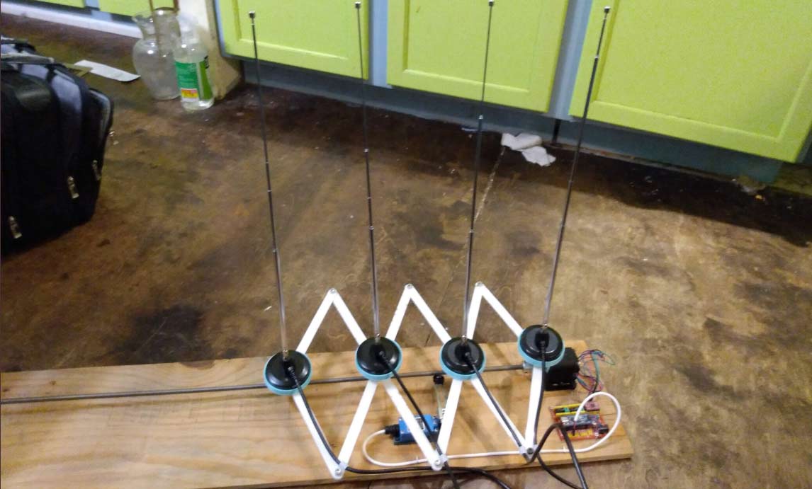
With coherent antenna array based direction finding, the optimal spacing between the antenna elements is proportional to the wavelength of the frequency being received. If you want to do RF direction finding on different frequencies, either multiple antenna arrays with different element spacings, or manually adjusting the antenna array with each frequency change is required.
Josh's design automates this problem with an antenna array that can adjust the spacing automatically. The design puts the antennas on an extending pantograph arm whose length is controlled via a threaded rod connected to a stepper motor. An Arduino microcontroller controls the stepper, thus allowing the spacing to be adjusted automatically.
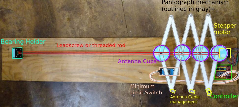
A full description of the build is provided in the document on GitLab titled "provisional_patent_application.pdf". From Twitter it appears that Josh (@CrankyLinuxUser) was unable to secure a patent for this design, so he has released the design for free under AGLP3. Most of the parts are 3D printed, and the CAD stl files all appear to be available on the GitLab. The Arduino microcontroller firmware is also available.
Thank you to Josh for releasing this design!


Couldn’t you do the same for circular arrays with threaded rods and a central gear turning all the rods in sync? Yes, it would be larger and bulkier, but I can envision how it could easily be done.
From reading the linked paper, the author only focuses on varying the spacing between the 4 antennas with frequency, but not on adjusting the element length with frequency. The antenna pattern varies further with the impact of the adjacent antenna(s), and the conductivity of the materials below the contraption, since he did not foresee a ground plane, or specify the length of the feeder coax which should be of equal length.
Patents (applications) require much more detailed explanation of the principles behind an invention, and a certain form to be accepted, which are missing in the paper. For example look at “Blade antenna with shaped dielectric“ https://patents.google.com/patent/US4509053A/en