Comparing LHCP and RHCP Reception of a Thuraya Satellite with an RTL-SDR and MIX4ALL
Over on YouTube Adam Alicajic 9A4QV (creator of the popular LNA4ALL) has uploaded a video showing a comparison of reception of Thuraya satellites with a LHCP (left hand circular polarization) and RHCP (right hand circular polarization) patch antennas. To receive Thuraya satellites, a LHCP antenna should be used, and Adam’s results show that using an antenna with the wrong polarization (RHCP) produces a signal that is as theoretically expected almost 20dB lower. Shortly after initially posting this Adam wrote in to comment on the following:
Thuraya LHCP original patch antenna have 2 patches stacked inside the panel antenna and the hand made RHCP patch antenna is made only of 1 patch. Theoretically, this should give the 3dB more gain for the Thuraya antenna.
The difference in the received signal due to polarization should be (theoretically) 20dB, thats RHCP vs. LHCP and I experience some 18dB of difference which is good result. Why not 20dB? First of all it is impossible to get 3dB more gain stacking the antennas, this is just the theory, more likely 2db in the practice.
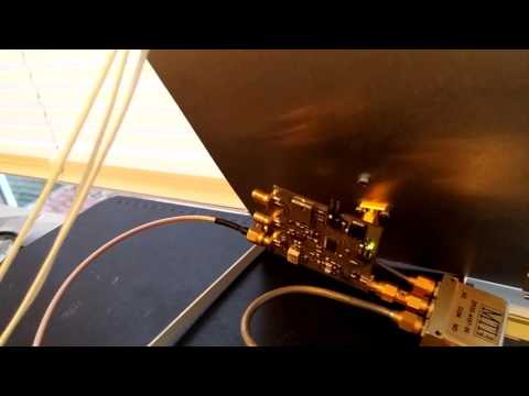
To receive the signals Adam uses the patch antennas, which are connected to the MIX4ALL (a downconverter that he is currently developing), which is then connected to a RTL-SDR dongle.
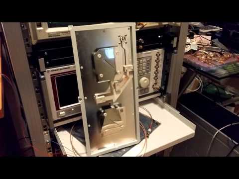
In the first video Adam shows the difference the wrong polarization makes, and in the second he shows some information about the Thuraya LCHP antenna he uses.


Good Video, Just wondering how you corrected RTLSDR for the conversion between dbFS and dbm. Is there an adjustable offset somewhere which can then be cal’d with a sig gen?
Hello Michael,
there is adjustable offset where you can edit the fft offset if you would like to make some measurements. This can be done simply by editing the SDRSharp.exe.Config file using the simple notepad editor. Almost on the top there is fftoffset value key that can be edited to suit your needs. just change the -60 value to any you like. You will need to play a bit with this settings to get the real figures.
Of course, you will need the calibrated signal source for that, and the calibration will be valid only for the certain setup, bandwidth, decimation. For everyday use this is not so important and dBFS is enough. At the end the dB ratio should be always the same.
Thanks Adam!