Building and Testing an L-Band Patch antenna for Inmarsat-C Reception
Over on YouTube Adam 9A4QAV (creator of the LNA4ALL and other RTL-SDR related products) has uploaded two videos showing his home made L-band patch antenna in action receiving Inmarsat-C and in the second video describing the construction of the antenna. Inmarsat is a geostationary satellite service that provides services such as satellite phone communications, broadband internet, and short text and data messaging services. Some of the messages on the Inmarsat STD-C NCS EGC channel are marine safety messages that are decodable with an RTL-SDR. This was discussed in our tutorial that we posted back in August. In that tutorial we used a prototype patch antenna that was supplied by Outernet.
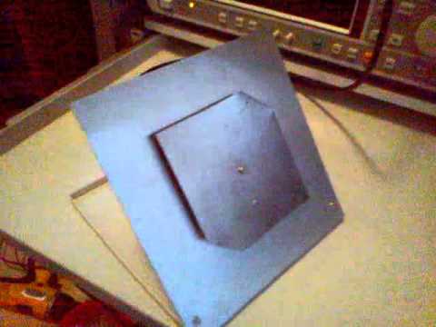
Adam’s home made L-band patch antenna consists of two thin sheets of conductive metal, cut to the right dimensions which are described in the second video. We have recorded the dimensions here (though be sure to double check with the video for correctness):
Reflector Size: 170 mm x 170 mm
Patch Size: 98 mm x 98 mm
Corner Trim: 21 mm from top right and bottom left corners
Coax Connection (Probe): 25 mm from bottom edge
Height of patch from reflector: 7 mm
The corners of the patch need to be trimmed to give the patch antenna right hand circular polarization (RHCP), which is the polarization used by Inmarsat Satellites.
The first video shows the patch in action with Inmarsat-C being received. In this video he also uses a simple downconverter to shift the 1.5 GHz Inmarsat-C frequency down to 300 MHz, which avoids the problem of the RTL-SDR not working very well at 1.5 GHz and above. In the second video Adam explains the dimensions of the antenna.


How can I change the design to get left hand circular polarization (LHCP)
Dont look isolated to me
Noticed the new Outernet L-Band patch antennas have a director. Anyone have any ideas on what the dimensions of the director should be? Also, would the spacing also be 7mm?
corner trim 21mm from corner at 45º? 21 mm long? how about a drawing?
Just put an L-Band Antenna design up on .
Thingiverse rendition of Adam (A4QAV’s patch antenna:
http://www.thingiverse.com/thing:2310033
saw that on Adam’s video for this, do you have this in a simple pdf to scale. I do not have the software to run your files.
I needed the same thing and a friend converted it to pdf for me. Make sure to measure it after it prints, you may need to turn off scaling in your printer settings:
https://owncloud.makerslocal.org/index.php/s/bvscCSrm6QXKAR9
Hi,
Could nylon pcb spacers cut down to 7mm be used?
I was thinking of using maybe one on each corner and one in the middle.
I’m going to use 0.8mm aluminium sheet, hopefully it will be sturdy
enough.
How accurate should the dimensions be because if either of the plates are not quite flat, the 7mm air gap won’t be easy to achieve?
What is used on the antenna in the video to seperate the plates and is it the only support?
Thank you
Andrew.
I have 3 questions: 1) The patch panel is connected to reflector size using metal screw or it MUST be isolated? 2) The center (signal) pin from SMA connector is direct soldered on patch panel? 3) Is possible to use PCB to build this antenna?
Tks!
Dear Jonis,
1) Isolated
2) Yes
3) Yes
Hi,
I also build one using these dimensions. I connected it to a R820T2 with a single LNA. I don’t get many signals close 1.5 GHz – only some single tones. After about 10 minutes R820T2 stops working (I get noise only). Waiting for MIX4ALL I guess..
Try this modified driver, see if it helps with your R820T2 failing at 1.5 GHz after 10 minutes https://www.rtl-sdr.com/beta-testing-a-modified-rtl-sdr-driver-for-l-band-heat-issues.
Hi, Very interesting videos.. I just built the patch antenna but haven’t tried it yet. Can you give more information on the frequency down-converter you used ? Perhaps a circuit diagram or link to one ? Many thanks.