KerberosSDR 4-Channel RTL-SDR Passive Radar with Peak Hold Display
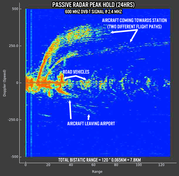
Recently we've been testing a simple peak hold for the KerberosSDR passive radar display. This results in some nice graphs that show aircraft and vehicle activity over time.
Passive radar works by using already existing transmitters such as those for HDTV and listening for reflections that bounce off of RF reflective objects. With a two antenna setup, it is possible to generate a bistatic range/doppler speed graph of reflected objects.
With the reference Yagi antenna pointed towards a 600 MHz DVB-T tower, and the surveillance antenna pointed to an airport we were able to obtain the graph below. The top two large traces show aircraft heading towards our station, whereas the bottom traces show aircraft leaving the airport. Also visible are multiple blips with smaller doppler speeds, and these correspond to vehicles.

The code on the KerberosSDR git will be updated in a few days time. We are also working on a more comprehensive passive radar tutorial that will try to explain concepts like processing gain, bistatic ranges and other important tips for getting good passive radar results. At the same time we're also working on improving direction finding ease of use by prototyping antenna switches for calibration, and working on getting 4-channel beamformed passive radar working which will allow us to plot passive radar returns on a real map.
The KerberosSDR is our 4-channel phase coherent capable RTL-SDR unit that we previously crowdfunded back in 2018. With a 4-channel phase coherent RTL-SDR interesting applications like radio direction finding, passive radar and beam forming become possible. It can also be used as 4 separate RTL-SDRs for multichannel monitoring. KerberosSDR is currently available from the Othernet store and Hacker Warehouse for US$149.95.
Could this system be adapted for tracking large insects, by fixing some kind of reflector to them, or would such a small profile simply be lost in the noise?
Very cool. You may want to consider implement a “speed gate” function, where the (abs(minimum)) and (abs(maximum)) doppler shift values can be selected for. That would allow you to filter out the uninteresting “noise” from the results.