Tagged: radiation pattern

Obtaining an Antenna Radiation Pattern with a Large Field, Android Device and RTL-SDR

An antenna's radiation pattern tells us how it radiates or receives electromagnetic energy in different directions, indicating the strength, directionality, and coverage area of its signals. These days, this is easy to simulate on a PC. However, getting real-world results can still be essential to ensure an antenna is constructed well. For commercial antennas, real-world testing is typically done in an RF anechoic chamber.

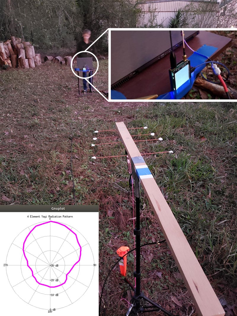
Over on Hackaday, Jenny List shows us an alternative method for measuring an antenna's radiation pattern: setting up an antenna in a large field and taking RF measurements at various locations around it using an RTL-SDR.

In the post, List tests an HB9CV two-element 144MHz Yagi antenna. As expected, the resulting polar plot from the measurements indicates that the HB9CV is a directional antenna.

We've seen a similar setup in the past, as shown in this post, where a NanoVNA was used to measure the antenna power.

Antenna Field Test Setup


Characterizing Yagi Antenna Directionality via ADS-B Reception

Over on his blog Alex Krotz has been investigating whether adding more passive director elements actually affects the directionality of his home made Yagi-Uda antenna. Instead of using modelling software, Alex wanted a more accurate result that took into account all the imperfections of his antenna.

His idea was to receive ADS-B signals with his Yagi and a dipole antenna, then compare the data received in order to determine in which directions the Yagi receives better than the dipole. To do this he first creates a standard 2D map of plane tracks collected over a 24hr period for both the dipole and Yagi. A gaussian blur is applied to the two maps in order to fill in blank space and the data is normalized. Then he simply subtracts the dipole plot from the Yagi-Uda plot. The resulting difference plot reveals a mapping of where the Yagi receives better or worse compared to the dipole in a 2D plane.

Directivity of the Yagi revealed by comparing against a dipole

Measuring the Radiation Pattern of a Yagi Antenna with a NanoVNA

On Hackaday we've seen an interesting post about Jephthai who has used a NanoVNA to measure the radiation pattern of a home made Yagi antenna. He began by initially modelling the Yagi using the MMANA software package, then building the antenna and measuring the SWR.

However, SWR is only partial information and tells us nothing about the actual gain and directivity / radiation pattern of the antenna. The radiation pattern tells us in which direction the antenna receives and radiates power best from. For a Yagi, we would expect the best reception gain to come from the front, with much less gain on the sides and rear.

To set up the radiation pattern measurement, Jephthai connected the Yagi to the TX port of the NanoVNA via a long coax cable, and connected an omnidirectional whip antenna to the RX port of the NanoVNA. The NanoVNA and Yagi are separated by a reasonable distance of 18' to ensure that the far-field radiation pattern is measured instead of the near-field pattern. He then measures and collects the S21 reading over multiple rotations of the Yagi.

The data is then plotted revealing a two dimensional radiation pattern for the Yagi. As expected gain is highest in the front, and weaker on the sides and rear. Jephthai notes that the radiation pattern mostly matches what the MMANA antenna modelling software predicted too.

Jephthai's NanoVNA Radiation Pattern Measurement Setup