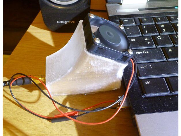
Over on the 3D printing sharing site Thingiverse, user “Way” has uploaded a 3D printer design for an RTL-SDR cooler block. The block works by allowing a PC cooling fan to blow air efficiently over the dongle body, removing any heat generated.
Cooling a dongle helps to avoid the L-Band problem, which is when R820T/2 units get hot and stop working about ~1.3-1.5 GHz. Generally passive cooling is enough (like with the thermal pad and metal cases used on our V3 dongles), but further cooling can apparently help increase sensitivity slightly although we are unsure if there is any statistically significant difference.
“Way” has made two designs, one to fit a 40 x 40 mm fan, and another to fit a 50 x 50 mm fan. The fan simply screws to the top of the block, and the dongle is placed at the bottom. Air is ducted over the dongle body and escapes out the back.
The R820T/2 RTL-SDR’s are known to have a problem that surfaces when trying to listen at L-band frequencies above about 1.5 GHz. As the dongle heats up the internal PLL appears to loose lock, causing reception to be lost above a certain frequency which is usually above around 1.5 GHz. There appears to be manufacturing variation between R820T/2 chips, so some dongles may exhibit this problem, whilst others do not, and some may fail at lower or higher frequencies than others.
This problem can be almost completely solved by cooling the RTL-SDR, and this is the reason we have added a thermal pad to the RTL-SDR dongles sold by us to aid with passive cooling via the metal case. In our tests this solves the problem for almost all dongles, but a few still do sometimes still exhibit this problem after running for a few hours.
Recently we were informed by a reader of RTL-SDR.com about a conversation on IRC where some users suggested modifying the RTL-SDR drivers to solve this problem. The suggestion was to modify the VCO current settings so that they were implemented in the same way as in the Airspy (which also uses the R820T2 but does not have this problem). Basically, in the Airspy the current is set at maximum on initialization, whereas in the RTL-SDR drivers it is set lower, and then bumped up if the PLL fails to lock. Setting it to maximum in the first place seems to help stop signal loss at L-band frequencies.
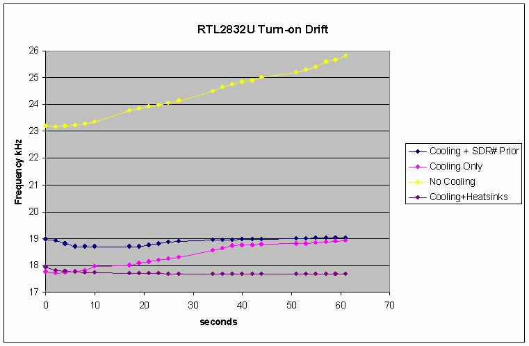
So far we’ve tested this change with a dongle that was known to be very bad at L-band. This dongle used to fail at 1.65 GHz after 20 seconds. With the driver change it fails after 2 minutes which is an improvement. With passive cooling via thermal pad and our metal case it used to fail after 15 minutes or so, but with passive cooling and the driver change it runs indefinitely.
If you’re having problems at L-band and would like to test this change then we’ve uploaded a modified Windows version of the driver on GitHub here https://github.com/rtlsdrblog/rtl-sdr/releases. It is based on Keenerds version of the RTL-SDR drivers. Simply download the .dll file and replace the current version in your SDR# folder, or other folder. Let us know if it helps you.
The main change made is r82xx_write_reg_mask(priv, 0x12, 0x00, 0xe0); is added to the init code, and r82xx_write_reg_mask(priv, 0x12, 0x80, 0xe0); r82xx_write_reg_mask(priv, 0x12, 0x60, 0xe0); are removed from the set_pll and pll check code.
Thanks to patchvonbraun, Youssef of Airspy and others on IRC for discussing this problem.
Passive cooling via thermal pad and metal case heatsinking resolves the L-band problem in most cases.
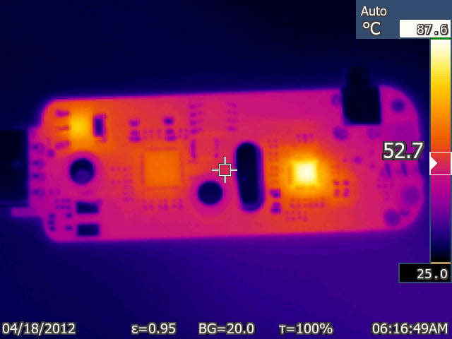
The RTL-SDR is known to get quite hot during operation and when it gets too hot reception of frequencies over 1.2 GHz can be degraded. Marko Cebokli wrote into us at RTL-SDR.com to show us some thermal imaging pictures that he has made of the RTL-SDR PCB. The images clearly show that the hottest part of the PCB is the R820T chip. The RTL2832U chip stays cool and the only other hot component on the PCB is the voltage regulator. In the post Marko also explains his conclusions on why the reception fails at frequencies over 1.2 GHz when it gets too hot.
The images show that the top of the R820T chip reaches a temperature of 85 degrees Celsius after just 10 minutes of operation. The underside of the chip reaches 68.9 degrees Celsius. Marko writes that these temperatures may be even higher when the RTL-SDR is placed inside the plastic case.
In general the RTL-SDR runs fine at these temperatures, but cooling the R820T chip will improve performance when tuning into signals that are higher than 1.2 GHz, for example with L-band satellites. Other RTL-SDR enthusiasts have cooled their RTL-SDR’s with thermal pads, heatsinks, fans and oil.
John Mills recently wrote in to us at RTL-SDR.com to show us how he cools his RTL-SDR by using a thermal gap pad stuck to the entire bottom of the RTL-SDR PCB. A thermal gap pad is a soft pliable material that is often used to interface between electronic chips and heatsinks. The gap pad forms into tight hard to reach spaces and conducts heat towards the heatsink. It is not electrically conductive, so the entire bottom of the RTL-SDR can be stuck to the thermal gap pad, which is then stuck to a metal heat sink.
John uses a thermal gap pad made by Bergquist, with part number GP5000S35-0.100-02. This gap pad is 0.1 inches thick, is easily cut with a craft knife and is tacky so it easily sticks to the heatsink and RTL-SDR PCB. It has a thermal conductivity of 5W/m.k. John uses the pad to help to cool the R820T, RTL2832U and voltage regulator chips. It has been shown in somepreviousposts that by cooling the R820T chip increased sensitivity can be obtained, especially at frequencies above 1.2 GHz.
He writes that if there is sufficient interest then he may consider selling strips of it on eBay. You can contact him at sdr_AT_milairuk.co.uk.
Below we’ve posted images of Johns thermal pad cooled RTL-SDR’s, along with his comments on them in the captions.
Open SDR – “Just held onto a heatsink with two pieces of string ! Then this sits on another larger heatsink using another piece of Gap Pad to hold it – this has been working in my garden shed now for over 2 years feeding ADSB data”Diecast Box SDR – “in this one I have made two small threaded metal clamps, lined with gap pad and tightened just enough to keep the PCB in good contact with the gap pad underneath and the diecast box. I use small BNC to MCX pigtails off Ebay to connect to the antenna socket. I also remove the LED and place through the box as can be seen.”Inside latest SDR / Latest SDR – “This is my latest version using a R820T2 version, and I have also fitted this with a TCXO. In this version I also used a 1Mohm and 47nF to ground the USB shield wire as in a previous post. This version only uses one metal spacer and the end of the PCB is secured by two M2 nylon screws / nuts. Case from China RF on Ebay.”Latest SDR – Outside
It is known that the R820T/2 is not as good as the older now rare and expensive E4000 tuners at frequencies above 1.5 GHz, and it is also known that sensitivity decreases as the temperature of the R820T/2 increases, especially at frequencies above 1.5 GHz.
MaxWorm tested an R820T, R820T2 and two E4000 sticks at receiving L-band frequencies. He found that one of the E4000’s performed the best, but surprisingly the other E4000 dongle was totally deaf in the L-band. The R820T and R820T2 dongles performed similarly – not as good as the best E4000, but not as bad as the worst. All tuners exhibited reduced signal strength when warm.
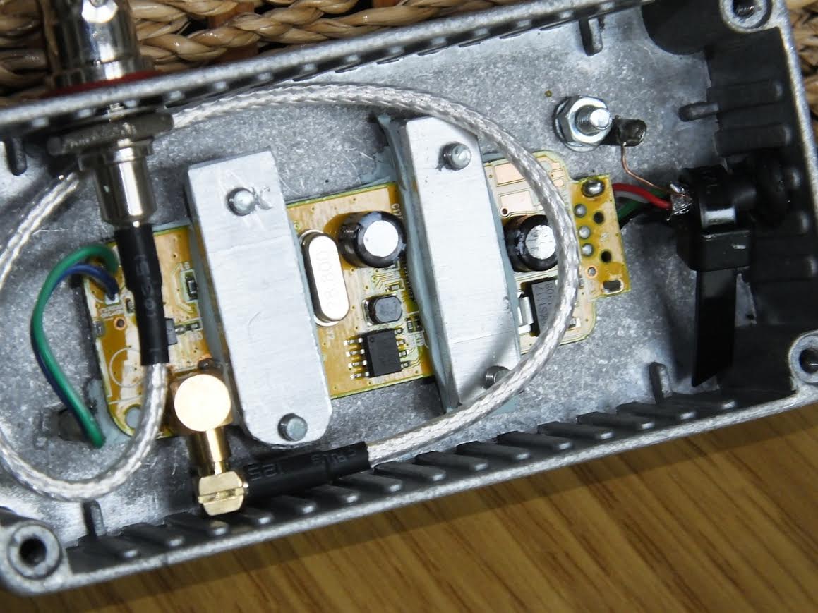
In another post MaxWorm also measured the temperature of the tuner chips in each of his units, and created a simple heatsink for one of his R820T2 dongles. His results show that the heatsink passive cooling works well, significantly cooling the R820T2 chip. His measurements are copied below:
R820T2 in Plastic case: R820T2: 77°C top / 74°C bottom RTL2832: 56°C top / 54°C bottom
R820T2 bare PCB: R820T2: 62°C top / 63°C bottom RTL2832: 43°C top / 42°C bottom
R820T2 in Alu-Case with Alu “L-Bridge” on Tuner: R820T2: top 37°C / bottom 47°C RTL2832: top 49°C / bottom 40°C
E4000 in plastic case: E4000: 37°C top / 37°C bottom RTL2832: 46°C top / 40°C bottom
bare E4000 PCB: E4000: 37°C top / 32°C bottom RTL2832: 40°C top / 37°C bottom
Other experimenters have previously applied fan cooling and oil cooling to RTL-SDR dongles to cool them and increase sensitivity.
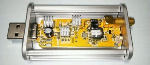
RTL-SDR with heat sink on the R820T2 chip connectoed to the aluminium case.L-Band Reception Results for an R820T, R820T2 and two E4000 dongles.
A pulsar is a rotating neutron star that emits a beam of electromagnetic radiation. If this beam points towards the earth, it can then be observed with a large dish antenna and a radio, like the RTL-SDR. The abstract of the paper reads:
This project sought to determine the minimum useful antenna aperture for amateur radio astronomers to successfully detect pulsars around the Hydrogen line frequency of 1420MHz. The technique relied on the collaboration with GM Gancio, who provided RTL SDR data of the Vela pulsar (B0833-45, J0835-4510) and others, collected with a 30m radio telescope. This data was processed to determine the achievable signal-to-noise ratio from which, the minimum useful dish size necessary for some effective amateur work, could be calculated. Two software packages were developed to do synchronous integration, a third to provide a power detection function and a fourth for spectrum analysis to recover pulsar rotation rate.
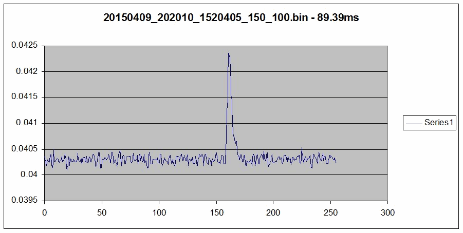
With their system the authors were able to detect and measure the rotation period of the Vela pulsar. Also, from their data they were able to estimate that the minimum dish aperture required to observe the Vela pulsar would be 6m, noting that the Vela pulsar is probably the strongest pulsar ever detected. They also write that by utilizing 5 RTL-SDRs to gather 10 MHz of bandwidth together with some processing that the minimum required dish aperture could be reduced to 3.5m.
The Vela pulsar pulse power integrated over a 50 second 100MB file, combining some 560 pulsar pulses.
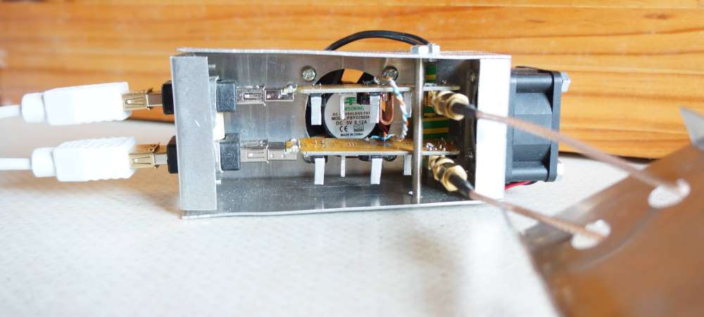
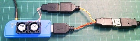
Results from air cooling the RTL-SDR.The air cooled and heat sinked RTL-SDRs
All of Peters papers can be found on his website at y1pwe.co.uk/RAProgs/index.html. He has many RTL-SDR radio astronomy related resources there, so check it out if you are interested.
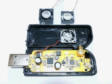
From his measurements, Nobu found that the internal temperature of the RTL-SDR can reach up to 70 degrees Celsius. So in order to cool the RTL-SDR Nobu has tried two methods. One involving using small cooling fans, and the other involving adding heat sinks to all heat producing components. It seems from the translation that he writes that the improved heat dissipation has extended his ADS-B reception slightly.
Over on his blog, Nobu has uploaded a post showing his experiments with a forced air cooled RTL-SDR dongle (note the blog is in Japanese so use Google Translate). A tiny fan from RS components is attached to the case of the dongle and draws power from the dongles own power regulator. Nobu also replaced the crystal oscillator with a flat packaged oscillator for a better fit.