Building An Open Source SDR Based Hydrogen Line Radio Telescope
Over on Reddit we've seen a post by u/ArtichokeHeartAttack who has been working on a hydrogen line radio telescope, based on an RTL-SDR dongle and horn antenna designs by the DSPIRA program, and the Open Source Radio Telescopes website (site appears to be down, linked to the archive.org copy). [u/ArtichokeHeartAttack] has documented their radio telescope building journey, providing a comprehensive top-level document that is able to point interested people in the right direction towards understanding and building their own Hydrogen line radio telescope.
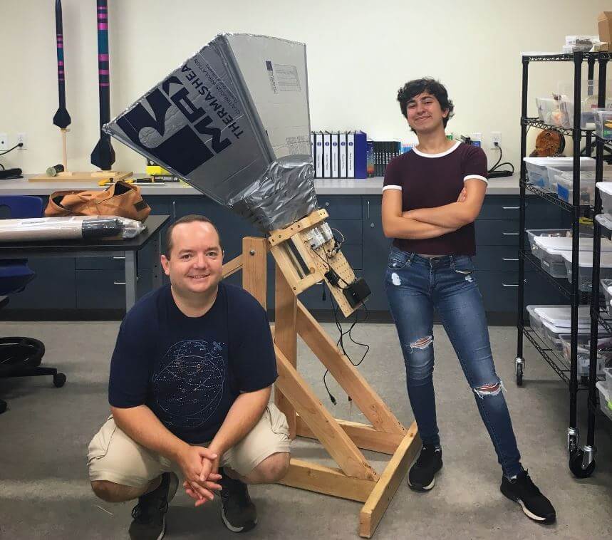
Briefly, their build consists of a horn antenna and reflector designed for the 1,420.4 MHz Hydrogen line frequency. The horn is built out of a few pieces of lumbar, metallic house wall insulation sheets and aluminum tape. The feed is made from a tin can and piece of wire. In terms of radio hardware, they used an Airspy SDR, GPIO labs Hydrogen Line Filter + LNA, and 2x Uputronics Wide band preamps, and a Minicircuits VBF-1445+ filter. For software processing, they used a GNU Radio flowgraph to integrate and record the spectrum.
The results show that they were able to achieve a good hydrogen line peak detection, and they were able to measure the galactic rotation curve doppler shift, and tangent points which prove that we do in fact live in a spiral galaxy.


Great Work! Have you seen the spiral arms of the Milky Way with your horn?
Hello, here is a link to the Hydrogen Line LNA that’s used in the project: https://gpio.com/collections/low-noise-amplifiers/products/hydrogen-line-lna . There’s also one with a built-in Bias Tee here: https://www.tindie.com/products/gpio/hydrogen-line-pre-filtered-lna-1420mhz-w-bias-tee/
I checked their document: the antenna has 18 db of gain and 20 deg aperture, so couldn’t a Yagi antenna be designed to these specs? I am thinking a smaller mount.
The authors did not specify if the calculated antenna gain is referenced to dBi(sotrophic) or dbd(ipole)?
Note: while an isotropic antenna has a gain of 0 dBi, a halfwave dipole has 2.15 dBi gain. Unfortunately even many manufacterer just claim a gain in dB and do not specify if the antenna gain is referenced to dBi or dBd.
So far I have seen only one L-Band Horn antenna design built by Bendix for SSR Parrots (1030/1090 MHz). I don’t have the dimensons and remember only the gain meassured to be 15 dB? and antenna elevation width @- 3dB points was 30°.
Without meassurement however it is quite bold to claim that any antenna achieved the calculated theoretical antenna gain, because there a re many things that can go wrong.
As for Yagis take a look at “A Homebrew Yagi for 1296 MHz DX” from DJ9YW http://www.ok2kkw.com/dj9yw_dubus0601.pdf , which gives you an idea of antenna gain variation of different designs, all meassured both under dry (3 dBd variation) and wet (5 dBd variation) conditions.
While it is possible to scale 23 cm designs for 1420 MHz, I wouldn’t dare to predict if the gain of a 23 cm design meassured in the 23 cm band can be reached at 1420 MHz or not, more likely not.
Sorry the Parrot Horn I quoted above was designed by Wilcox and can be seen at page 16 fig. 28 the elevation pattern in and fig. 29 in the CEPT WP provided to WG SE7 under Reference SE7(19)182R1 with the title “Elevation contour pattern for aeronautical systems in the band 960 to 1215 MHz – aircraft antenna – Amendment 2”.
Lumbar or lumber?