Using a LimeSDR To Detect Aircraft Reflections from a 2.3 GHz Beacon
Over on his blog author Daniel Estevez has described how he's been listening to aircraft reflections from a 2.3 GHz 2W beacon. The beacon is 10km away from Daniels location and transmits a tone and CW identification at 2320.865 MHz. As aircraft fly nearby to his location Daniel was able to observe aircraft reflections of the beacon, and was able to match them with ADS-B position and velocity reports.
The hardware that he used was a LimeSDR and a 9dBi 2.4GHz planar WiFi antenna patch. By aiming the antenna away from the transmitter, and using his car as a shield to block the transmitter he was able to receive some reflections. Daniel recorded several reflections including one produced by a nearby car.
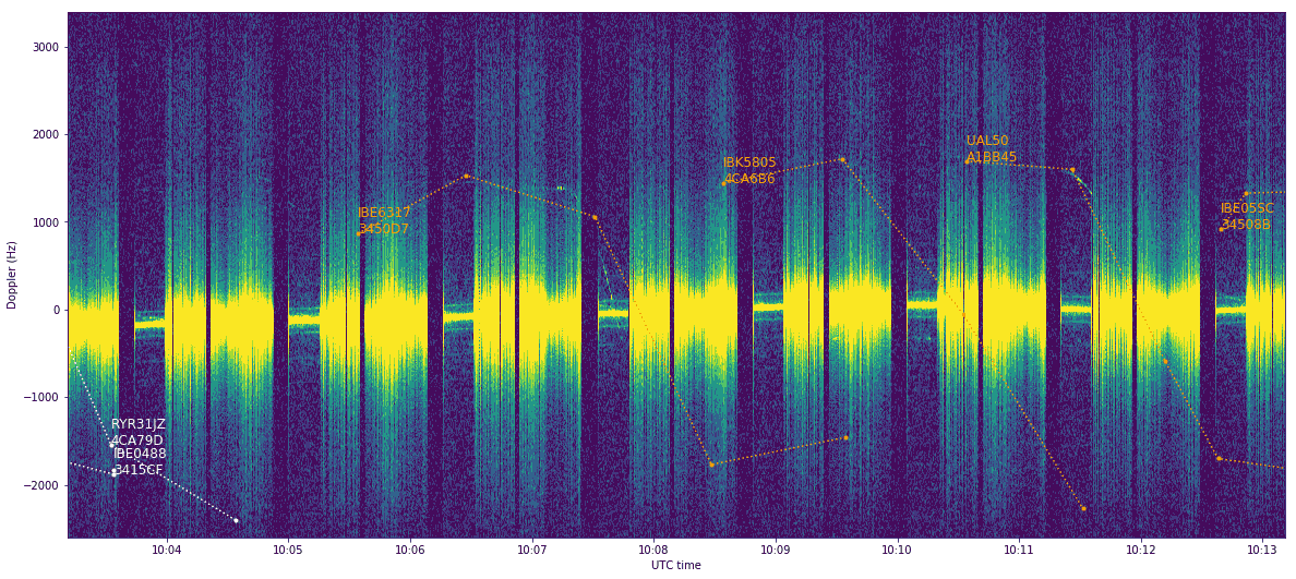
By combining his results with ADS-B data he was able to superimpose the results, and color aircraft tracks by either a negative or positive doppler shift which was observed from the reflection. By combining the ADS-B data with the time stamps, he was also able to mark the reflections from each aircraft.


i cant wrap my head around that graph / plot. can any help explain in simple terms ?
The plot depicts reflections and identifies the doppler shift in frequency (see http://rfcafe.com/references/electrical/doppler.htm ).
From what I know, without knowing if the plane were moving toward or away from him, the elevation angle between him and the the planes and the planes speed over ground, it is impossible to say if the doppler shifts are plausible, since I would have assumed to see at least a clear placement of reflections of the planes to be either in the positive or negative doppler shift range, unless planes were overhead and the speed close to 0. In between the aircraft reflections I would have assumed that there is no doppler frequency or a flat line at 0 kHz which is not he case.
Does anyone have an ides why the display is like it is?
Look for previous posts for kerberosSDR then look for passive radar youtube videos
https://www.rtl-sdr.com/hydrasdr-preview-a-4x-coherent-rtl-sdr-for-direction-finding-passive-radar-and-more/