Using an RTL-SDR to decode VOR Aircraft Navigation Beacons in Real Time
VOR stands for VHF Omnidirectional Range and is a way to help aircraft navigate by using fixed ground based beacons. The beacons are specially designed in such a way that the aircraft can use the beacon to determine a bearing towards the VOR transmitter. VOR beacons are found between 108 MHz and 117.95 MHz, and it's possible to view the raw signal in SDR#.
Over on RadioJitter author Arnav Mukhopadhyay has uploaded a post describing how to decode VOR into a bearing in real time using an RTL-SDR dongle. His post first explains how VOR works, and then goes on to show an experimental set up that he's created using a GNU Radio program. With the software he was able to decode an accurate bearing towards the VOR transmitter at a nearby airport.
Arnavs post is a preview of an academic paper that he's worked on, and the full paper and code is available by request on the radiojitter post. We've also seen on YouTube that Arnav has uploaded a video showing the software working in action, and we have embedded it below.


It looks like the error stays around -30 degrees, why is that?
I looked into this and found the reason. The Frequency Xlating FFT Filter adds an additional phase delay because of the low pass filter. The FM receive block contains an additional audio low pass filter that adds another phase delay. Even the hilbert transform seems to add some more delay to the FM signal. The trick is to apply the same filtering to the other path to add the same delay there. The improved GRC flow graphs can be found on github (reald/sdr-collection) now. There are also a flow graphs for generating test signals and an improved version of https://www.rtl-sdr.com/receiving-vor-radio-navigation-rtl-sdr-gnu-radio/ .
Github: reald/sdr-collection
73
DL9CAT
The blog content is updated while considering all the feedback and adding more clarity to certain sections. Now the source code is published in github.
PS²: The variations in Depth of modulation vary between VOR and DVOR, and also for Id and Voice channel vary
-conventional VOR,percentage of amplitude modulation of the 9 960 Hz subcarrier shall not exceed 5 per cent.
– DVOR, the percentage of amplitude modulation of the 9 960 Hz subcarrier shall not exceed 40 per cent
(D)VOR voice channel
Ident tone 1020 Hz±50 Hz depth to which the radio frequency carrier is modulated of max. 10%, with Voice channel 20%,
and Voice channel 300 to 3000 Hz, peak modulation depth of the carrier max. 30 % AM
Actually, the author is receiving a Doppler VHF Omnidierctional Range (DVOR) and not a (C)VOR as he describes in the text.
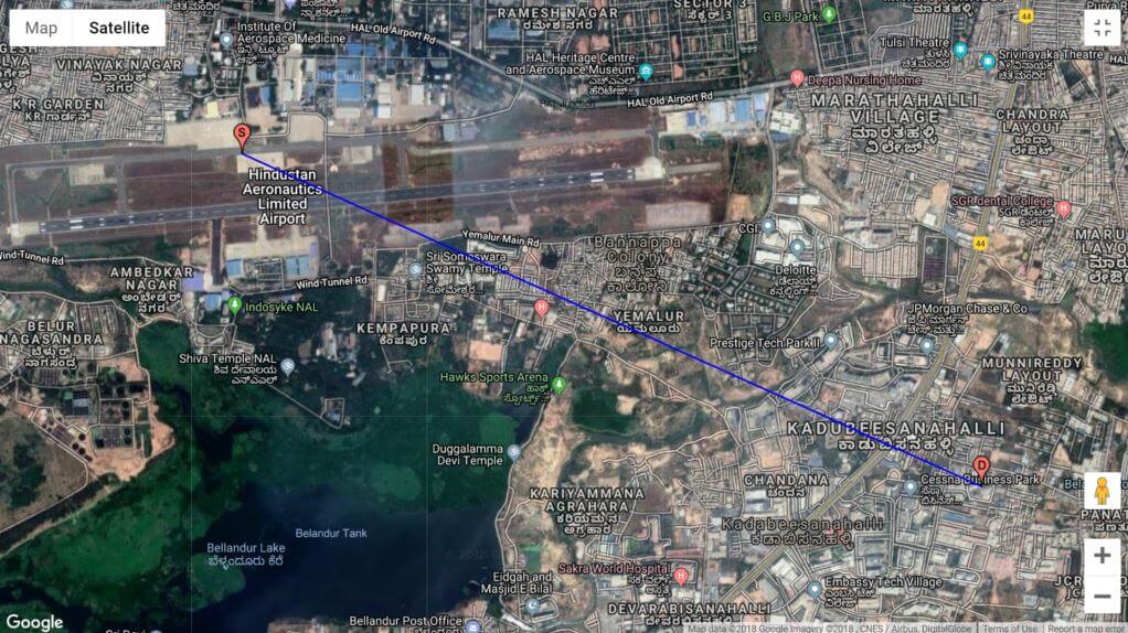
The location of the DVOR on 115.500 MHz is south-east of the runway center and not north of the runway as shown as end of radial. The DVOR can be found in google maps at 12°56’57.8″N 77°40’50.9″E, while ourairports.com identify 12° 56.982021′ N, 77° 40.859985′ E (2,908 ft / 886 m MSL) as the location for DVOR/DME BBG 155.500 MHz.
A DVOR consists of a large counterpoise with a ring of min 40 to today 50 Alford loop antennas in a circle around the center reference antenna. Simplified explanation for the difference between DVOR and VOR is:
-DVOR switch one signal between opposing antennas, rotating 360° around the Doppler basis to produce the doppler effect, while the center antenna is used as reference antenna,
– VOR initially had 4 and later 5 Alford loops on a counter poise in the FAA designs, while later designs from other manufacturer consist of 2 or more separate vertically stacked antennas for generating the horizontally polarized rotating and reference signal. Reference and rotating cardioid generation are exchanged between DVOR and VOR. The rotating cardioid was first generated by a motor driven goniometer. One design used a short horizontally dipole driven by a motor, inside a polarization cage to ensure only horizontally polarized radiation was generated.
Alford loop antenna are horizontally polarized omnidirectional antenna design described by Alford first in electronic design ~1940.
VOR and DME are ICAO standardized navigation aids since 1949, and are defined in ICAO SARPS Annex 10, and later in Annex 10 Vol.I. Note: the 1949 DME was replaced later, since 1960 by DMET (T for TACAN based parameter, without that ICAO adopted the bearing information from TACAN) which are called today DME/N (for a narrower signal than DME) and DME/P (Precise).
For difficult terrain DVOR development started about 1955 in USA, UK (e.g. Plessey) and Germany (Alcatel for BFS), with mature DVOR designs in operational use since the early 1960’s. Counterpoise diameter and height AGL varies. If the author has direct Radio Line Of Sight, that the displayed radial should not fluctuate so rapidly.
If this is for an academic paper it shows bad research on the authors part, and obviously lack of understanding on his professors part, when the difference between VOR and DVOR is not identified. The author describes generation of a VOR signal, while he should describe DVOR generation. Adiagramm can be found e.g. in FAA R&D report CT-81/194, TEST AND EVALUATION OF SOLID-STATE DOPPLER VERY HIGH FREQUENCY OMNIDIRECTIONAL (DVOR) DISTRIBUTOR ASSEMBLY
PS.: The year numbers that I quoted are from memory.
PS².: DVOR provide an accuracy of about ±1°.
Since the bearing fluctuates so rapidly, the replication of the VOR receivers filtering needs adjustment.
I also tried to inform the author by trying to post these comments/information several times unsuccessfully on the authors webpage, but they were not accepted.
Very informative comment, thank you!
This is not an academic paper, just a PDF report. The fluctuations are high because of electrical disturbances that increases heavily during evening time, which also results in degradation of even the commercial FM signal.
snn47 is correct (your comment is very informative, bad on my part), that this is DVOR with +-1 deg of error. If you are trying to contact me, take my mail id (gudduarnav at gmail dot com), with any suggestions or corrections.
Also I am updating the article with all the changes. It will take a few days to update the article.
By the way, as far as receiver design is concerned,both DVOR and CVOR detector seems to be the same, only -ve sign in detected phase.
Thanks snn47
Arnav