Using an RTL-SDR to decode VOR Aircraft Navigation Beacons in Real Time
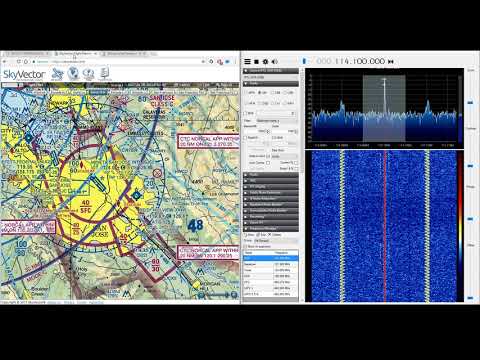
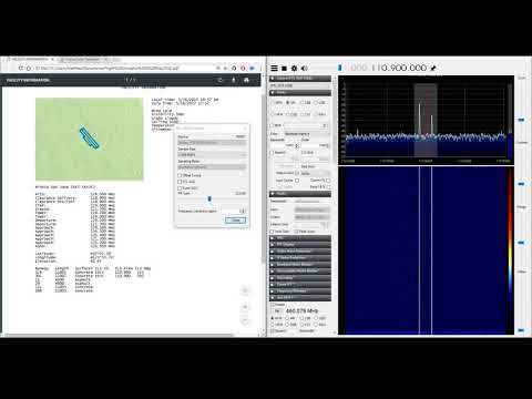
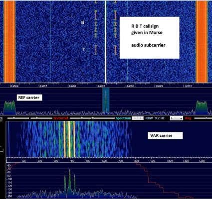
VOR stands for VHF Omnidirectional Range and is a way to help aircraft navigate by using fixed ground based beacons. The beacons are specially designed in such a way that the aircraft can use the beacon to determine a bearing towards the VOR transmitter. VOR beacons are found between 108 MHz and 117.95 MHz, and it's possible to view the raw signal in SDR#.
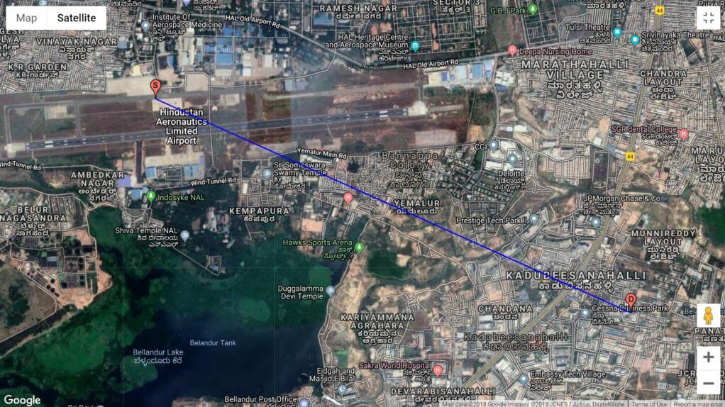
Over on RadioJitter author Arnav Mukhopadhyay has uploaded a post describing how to decode VOR into a bearing in real time using an RTL-SDR dongle. His post first explains how VOR works, and then goes on to show an experimental set up that he's created using a GNU Radio program. With the software he was able to decode an accurate bearing towards the VOR transmitter at a nearby airport.
Arnavs post is a preview of an academic paper that he's worked on, and the full paper and code is available by request on the radiojitter post. We've also seen on YouTube that Arnav has uploaded a video showing the software working in action, and we have embedded it below.