JR Magnetics Small Ultra Wide Band 750 MHz to 6 GHz Antenna for SDRs on Kickstarter
John from JR Magnetics has written in and wanted to share his Kickstarter for a US$50 ultra wide band antenna that he has designed. The size is a just little bit bigger than two credit cards and the advertised coverage is from 750 MHz up to 6 GHz with a VSWR of less than 2.0.
John's Kickstarter text reads below:
About
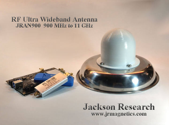
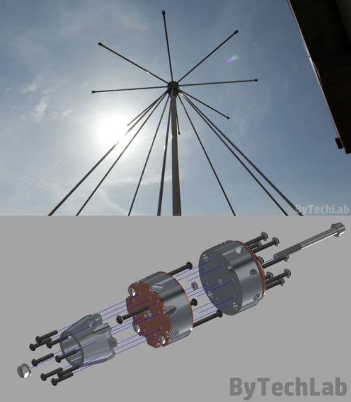
I was never satisfied with the commercially available wide band antennas. They were all too large or did not have suitable VSWR over the frequency range generally required by SDRs. I read many research papers and ultimately made a omni-directional ultra wide band antenna, but it was too expensive for most people. Details regarding that antenna can be found at https://www.rtl-sdr.com/constructing-a-3d-printed-wideband-900-mhz-to-11-ghz-antenna/
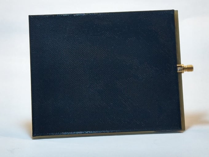
However, a bi-directional antenna was good enough for most people, so I have made a flat one. The antenna I ended up with is 5 inches by 4 inches and about 3 mm thick with an SMA connector. It is quite definitely not a square patch antenna, which usually has a narrow bandwidth.
This antenna has a VSWR measured to be under 2.00 from around 750 MHz to over 3 GHz. It simulates to have a VSWR under 2.00 out to over 6 Ghz. This is enough for most of the available SDRs. It works very well with WiFi, Bluetooth, Zigbee and other systems within the bandwidth.
Existing Antennas
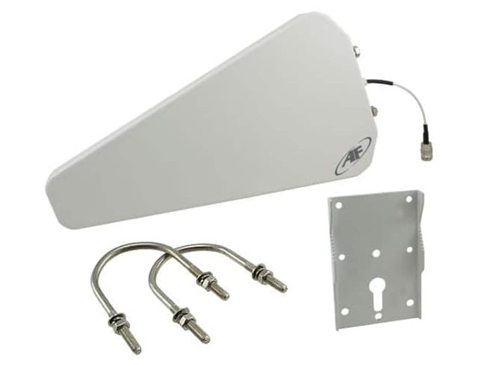
The log antenna, Figure 2, has a wide bandwidth, but it is specified as having ranges, because the VSWR rises over 2.00 several times over that range. The antenna measure sover 40 centimeters long, which is problem for me in a laboratory setting. It is too large to fit anywhere and wants to be permanently fixed to a pole or something like that.
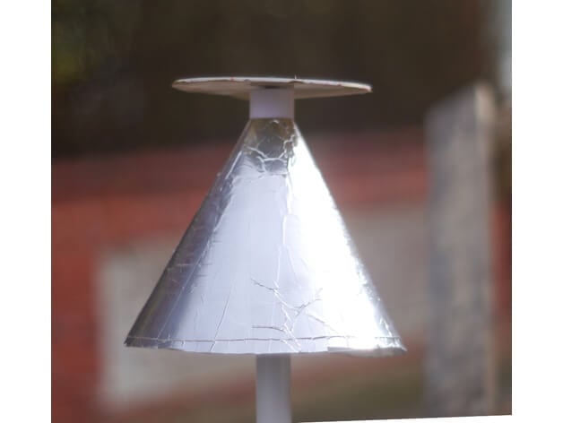
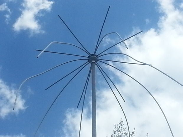
The other antenna I have is a discone type device, Figure 3. It is huge. There is not practical for it to fit on a lab bench around various RF devices. It is measures around 28 centimeters at its base. It needs to be elevated above any ground planes, which complicates a laboratory environment with metal bench tops. I have it sitting on a shelf above the computer monitors on the opposite side of the room away from the lab bench. This does not work well when I am trying to deal with wireless devices connected to USB hubs on the bench with short range features.
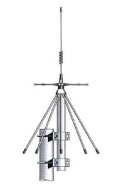
Figure 4 shows the Flat Antenna next to the Log Antenna for a size comparison that illustrates just how much space saving there is with this new device. This is no small feat. This Flat Antenna is useful around all manner of RF devices on the bench without causing space issues, getting in the way of instruments and couples well with all of the wireless devices I am using. It is small enough with a convenient shape for moving it around and keeping it above a metal bench top. It only needs to be a few centimeters above any ground planes when perpendicular, not horizonal.
Due to its size and shape, near field problems have not been a problem, as with the other antennas. The antenna is quite directional, which is not much of a problem, since the RF bounces around all over the place. A Faraday shield is the only way to keep this device from picking out everything in the vicinity. The neighbors IoT devices create mountains of RF clutter. This antenna picks up all of it. If you only want restricted bandwidths, band pass and reject filters can be used. The load impedance is 50 Ohms across the band making an excellent match for all of the filters I have here.

Specifications
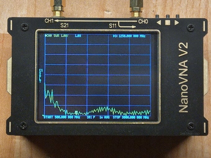
Figure 5 shows the VSWR as measured by the NanoVNA Version 2. It only goes out to 3 Ghz. The device must be calibrated before use, or you will get extraneous results. I am told the VSWR never goes above 2.00 until after 6 GHz. This is a remarkable antenna. I never found anything comparable to it on the Internet.
It can be used for all wireless and SDR applications normally within the 750 MHz to 6 GHz bandwidth. This is not guess work or speculation. The network analyzer shows the response clearly.
The antenna is 5 inches long by 4 inches wide by roughly 3 mm thick, not counting the SMA connector.
What You Get
You get one (1) antenna, as shown in Figure 1, for each US$50. You cannot do this yourself for that price. Your time alone is worth more than that after you do the calculations, simulations and prototyping. You also would have to deal with fab shops to get this done correctly, which is not always convenient for many people.
In other words, this is a remarkable Ultra Wide Band Antenna at a remarkable price.
Engineering
This has already been done. I have a Masters Degree in RF Engineering. I also have all of the simulation tools that are not available to most people, with the exception of some university students.
Manufacturing
I have sources that I use all the time. I just put this one into the queue. We also have a minimum order, which is why we Crowd Fund this operation.
Timeline
Once in the queue, it takes about two (2) weeks. After that, we are only concerned with delivery time. We intend to use ordinaty Postal Service mail, to keep the cost down, so time of delivery may vary depending upon the destination.
Risks and challenges
We already have laboratory results, so there is nothing to risk in performance. The only other thing that could be troublesome is the lead time by the vendor that manufactures the main component or any delays caused by the Postal Service.
UPDATE 16 Dec 2020: John has provided us with this document that addresses a few questions people had about the antenna.