A Tutorial on Receiving HRPT Weather Satellite Images with an SDRplay RSP2
Over on the SDRplay forums user 'RSP2user' has put up a quality post describing how he receives HRPT weather satellite images with his SDRplay RSP2. HRPT stands for 'High Resolution Picture Transmission' and provides a much higher resolution image compared to the APT weather satellite images typically downloaded from NOAA satellites. Somewhat confusingly the picture quality of HRPT is similar to LRPT (low rate picture transmission) which is used on the Russian Meteor M series weather satellite. HRPT provides 1.1 km resolution, whilst LRPT provides 1 km resolution.
Currently there are multiple satellites broadcasting HRPT signals including NOAA 19, NOAA 18, NOAA 15, Meteor M2, Fengyun 3B, Fengyun 3C, Metop A and Metop B.
The difference in difficulty of receiving APT and LRPT versus HRPT transmissions typically occur in the L-band at about 1.7 GHz, and requires a directive high gain antenna with tracking motor to track the satellite as it passes over. This makes these images many times more difficult to receive compared to APT and LRPT which only require a fixed position antenna for reception at the more forgiving 137 MHz.
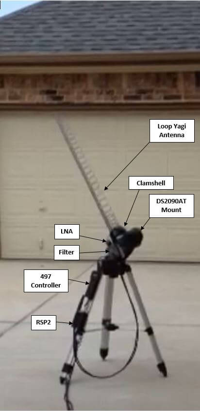
Over on his post RSP2user shows how he uses a repurposed Meade Instruments telescope tracking mount and controller to drive the tracking of a 26 element loop Yagi antenna. A 0.36dB noise figure LNA modified with bias tee input is used to boost the signal and reduce the noise figure. The signal is received by a SDRplay RSP2 and processed on a PC with USA-satcoms HRPT decoder software, which is available for purchase by directly contacting him. The HRPT signal bandwidth appears to be about 2.4 MHz so possibly an RTL-SDR could also be used, but it might be pushing it to the limit.
If you are interested, RSP2user also uploaded an APT weather satellite image reception tutorial on another post. This tutorial shows how to build a quality quadrifilar helix antenna as well.


I have a DS2090AT telescope mount and I am looking at adapting it to a helical antenna. One challenge I am finding has to do with how to get the antenna to have more than 45 degrees of travel along the vertical path, since the conventional helical antenna ground plane hits the mount and you would have to extend the ground plane away from the mount for that not to happen. If you do move the ground plane out from the mount, the whole antenna is moved out and then the mount becomes unbalanced and does not operate correctly. Whomever wrote the article had a great idea in leaving the DS2090AT mount alone and not modifying it so either a telescope tube or an antenna can be clipped in. Given the ground plane issue, does anyone have any suggestions on how to get a helical antenna to fit on the DS2090AT telescope mount and achieve the full range of vertical travel?
There is something to be said for actually building things and seeing the mechanical, electrical, and RF interactions first hand. Looks like your only option is to trim off part of the reflector “ground plane” on the side next to the arm of the mount to get clearance and just see how that impacts the antenna performance. One note though, there is a new post on the SDRplay forum showing the same loop Yagi antenna and mount setup for use with geostationary satellites for HRIT and LRIT image reception. The GOES 13, 14, 15, and 16 satellites are discussed and these apply a linear polarization. By using a helical antenna, you will lose 3 dBi of gain for reception of linear signals and for geostationary satellite image reception, every dBi of gain from the antenna counts. If you intend to apply the same antenna for HRPT and HRIT/LRIT image reception (as mentioned in the original HRPT article on the SDRplay forum), then you may want to consider a linearly polarized antenna instead of a helical antenna, since you would likely end up doubling the length of your helical antenna or adding an array of at least two helical antennas to perform the same as the loop Yagi antenna in the latest article on HRIT and LRIT image reception, when attached to an unmodified Meade DS2090AT mount. Considering the dual purpose application of one antenna (HRPT plus HRIT/LRIT) and having the antenna mechanically work well with the DS2090AT mount, it looks like this may be why the author of the articles chose a loop Yagi antenna for the specific application.
Working on a helical antenna for HRPT similar to the 1.5m helical antenna by Arne Van Belle here: http://www.g-romahn.de/wxsat/download/helical.zip . If anyone builds one of these helical antennas and gets it to work well with the DS2090AT mount, please post results. For comparison, images from the loop Yagi antenna are posted at the link in the article above. Also, if anyone gets a helical antenna to work well with the HRIT and LRIT signals from geostationary weather satellites, please post images and results.
After spending a great deal of time, effort, and testing on a helical antenna and a Yagi Loop antenna, the outcome has been that the helical antenna does not perform near as well at the Yagi Loop antenna of comparable length. The biggest issue with the helical antenna is that it picks up a lot of terrestrial interference that is outside of the beam. Also, there is a new article on the SDRplay web site applying a low cost grid parabolic reflector antenna that also looks promising: https://www.sdrplay.com/community/viewtopic.php?f=5&t=3262
Nice and detailed article but going quickly through the post I am surprised that he uses the linear polarisation for the RHCP reception. When linear pol.antenna is used for receiving the cir.pol it does not matter how you will polarize your antenna, so placing the antenna for 45deg. pol. like in the article does not have any benefit.
This antenna is 181cm long and the same, if not better results can be achieved using the half size (92-110cm) long, end feed helical antenna (25 turn helix). This will make less stress on the motor turning the antenna. Design of helix is less critical and wideband.
Perhaps you could build what you are suggesting and post the results for review. A lot can be learned by actually building things. For example, how do you plan to keep the lengthy and small diameter helical antenna sufficiently straight without weighing too much? You will find that a metal boom will interfere with the helical antenna, an acrylic or PVC boom will droop too much or weigh too much, and wood, unless prepared properly, can absorb moisture and impact the antenna gain. Also, you need to take into account that a helical antenna typically has a 150 ohm impedance, so you will need to add an impedance matching solution or lose additional gain. Also, your comments indicate that you may be using a text book or an online calculator for your suggested helical antenna design. Most helical antenna calculators and text books providing equations for helical antenna design are based on original work by J.D. Kraus. Many who have built and tested helical antennas using these equations believe that the results from the equations for antenna gain are 3dBi optimistic. So if you actually build what you are proposing, you may find that it does not develop the gain that you are looking for without doubling the length of your helical antenna. So feel free to actually build a helical antenna as you are suggesting and let us all know how well it works. Who knows, you may come up with a really great solution.
Maybe I already build such an antenna and I am writing based on the experience? Have you thought about that?
If you ever build the antenna I propose, you will find out the helical antenna is quite wideband and error forgiving regarding the measures. Yes, the metallic boom should be used (aluminum square) and the standoff insulators made of RG-213 center insulation to make the construction simple. Wire or strip can be used for the helix, metal strip is a much better option if this is available (copper). Reflector with the rim to add some directivity. Matching is simple. Have you measured how good is the loop yagi from the article? I do have the same antenna for 1296Mhz and I can confirm that it must be tuned and the antenna is quite narrow. Tuning the loop design is not so easy. matching helix is quite simple adding some capacitance on the 1/8 of the first turn. You can get an almost perfect match for the desired frequency. And now the numbers. I am not using the calculators for the antenna, just the basic math. 25 turn helical antenna will deliver 16.5dBi of the gain (circular polarization). Depending on how step you will wound the helix (0.21-0.25 lambda/turn) the antenna should be 5.25-6.26 lambda long. The antenna form the article is 10 lambda long and delivering 20dBi. Due to polarization mismatch (linear over circular), there is 3dB loss and the result is 16.5 against the 17dbi. Well, a simple practical knowledge tells us that for the 3dB gain you need to double the size of the boom. So here we are with the gain. The practical limit for the helical antenna is 7 lambda. For the higher gain, two or more should be stacked/combined. This is what you can see on some serious helical antenna systems too.
The p
Good points, Adam. Also there is an additional improvement achieved by stacking two helicals. The feed impedance of a single helical antenna is given by 140 x Circumference / Lambda Ohms. most people construct their helices to have a circumference equal to the wavelength at the frequency of interest, giving a feed impedance of 140 Ohms, therefore a stacked pair, correctly phased (just parallelled) gives us 70 Ohms – a pretty good match for the 75 Ohms required by the RTL-SDR. If anyone worries too much about the remaining small mismatch, just increase the circumference by 7% (only about 12mm in the above case of HRPT), although it really isn’t necessary.
And yes, in case you hadn’t guessed yet, I am a big fan of the axial-mode helical antenna.
Julian
Nice. Have been thinking about grabbing one of the (many, many) used Celestron mounts off of eBay to experiment with UHF satellite tracking.
I spend a lot of time thinking about trying to build tracking antennas for NOAA APT because flying-v-dipoles and QFHs get boring and need more robot parts. But unfortunately VHF antennas are kind of heavy. Microwaves mean being able to use smaller motors / servos to move around gain antennas!