RTL-SDR.COM Broadcast FM Band-Stop Filter (88-108 MHz Reject) Now for Sale + RTL-SDR V3 Dongle Availability
In our store we have just released our new broadcast FM band-stop filter. The cost is $14.95 USD with free international air mail worldwide shipping. (Of course you may choose to upgrade to faster shipping if desired). This product is currently only shipping from our warehouse in China and is not available on Amazon for the time being.
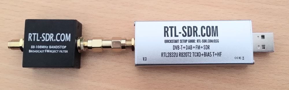
The filter comes in a 2.8 cm x 2.8 cm x 1.3 cm aluminum enclosure and uses female SMA connectors on each end. Included in the package is also a SMA male to SMA male straight barrel adapter.
Important Shipping Note: Please note that right now it is the long “Golden week” holidays in China (1 – 7 Oct), so this product will probably ship out next week and there may be some delays relating to heavy “catch-up” mail volumes around this time.
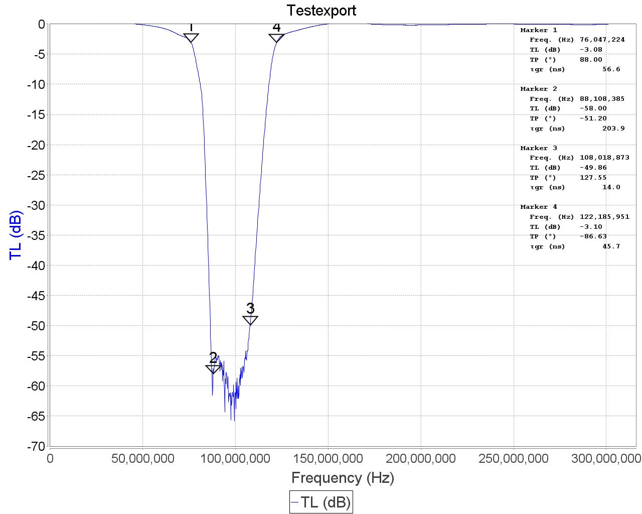
This filter rejects signals between 88 – 108 MHz with around 50 dB or more attenuation. A broadcast FM band-stop filter is very useful for use with SDRs as in some areas broadcast FM signals can be so strong that they overload the SDR, causing very poor performance in other bands. You can tell if this is the case for you if you see images of BCFM stations or interference that looks like a WFM signal at other frequencies when you turn up the gain.
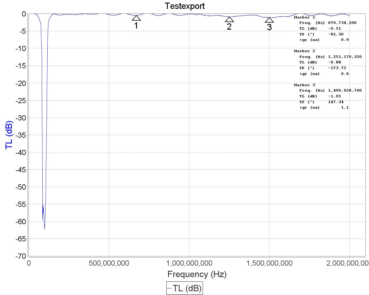
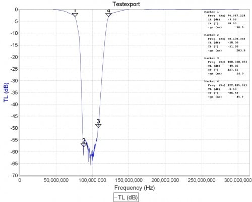
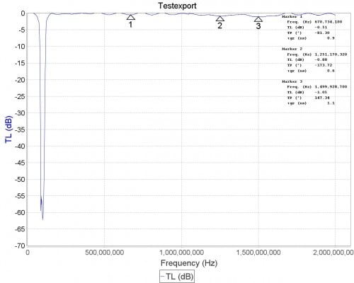
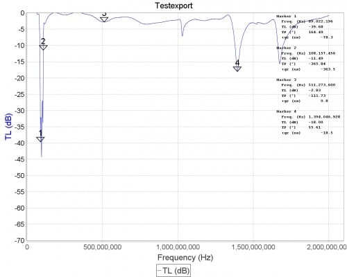
The filter is based on a simple 7th order Chebyshev design. The 3 dB roll off is at 76 MHz and 122 MHz. 88 MHz is attenuated by almost 60 dB, and 108 MHz is attenuated by 45-50 dB. Outside of the pass band the insertion loss is practically zero below 500 MHz, less than 0.5 dB from 500 MHz – 1 GHz, and below 1.5 dB between 1 GHz – 2 GHz. Between 2 – 3 GHz performance degrades slightly, but insertion loss remains below 1.5 dB for most frequencies. The filter can also pass up to 80 mA of DC current (probably can do more) and has negligible DC resistance.


Below we show a comparison of what a cheap $5 TV FM band-stop filter looks like on the network analyzer. You can see that the stop band is attenuated by significantly less, and the insertion losses on other frequencies are much much larger.


RTL-SDR v3 Availability Note: Our next batch of RTL-SDR v3 dongle stock should be available in 1-2 weeks (there is a delay with restocking due to the Golden week holidays). Production has completed, and we are only waiting for delivery of this stock. Batch 2 includes minor enhancements including slightly tweaked capacitor values, an additional decoupling cap and a fuse on the bias tee.


Huge difference with this notch filter for both Rx and Tx! I setup a Diamond D220 antenna and pretty much thought it was unusable. When I connected this filter all of the sudden I could hear stations that were not coming through at all without it. I know it’s not meant for transmission, but I had a simplex QSO with a station in San Diego last night (I’m in Los Angeles) with this Diamond antenna and a 5W Quansheng handheld radio.
Noob question here, does the broadcast fm band stop filter requieres bias tee enabled?
No. It is just a couple of passive components.
I have not found an answer to a very important question: is this FM Notch filter symmetrical?
Can exchange Input to Output?
yes, it is.
Okay, but so why when I swapped the input and output positions did the FM-radiostation rejection level change?
If Filter is used in Strong FM Broadcast signal level Areas, Little to No Filter effect will occur without Additional RF Enclosure Shielding & checking for In/Out signal Directional Effect…..This Explains various customer product Performance reports..
The Filter is very RF Leaky with Plastic enclosure….This Explains various customer product Performance reports..
The filter is shielded in an enclosed metal case.
I use one here and it’s fully enclosed in a metal case.
“narrowband notch filter” – totally symmetric, either side can be the input/output.
“wideband notch filter” – is an asymmetric circuit, you have a RF in side and a RF out side of the circuit.
Search for “wideband notch filter calculator” in your search engine to see example circuits, one circuit is symmetric (narrowband) and one is asymmetric (wideband).
You have completely confused me 🙁
I don’t know what kind of filter by RTL-SDR it is, “Notch Filter” or “Broadband notch filter
The FM filter by RTL-SDR, says above “The filter is based on a simple 7th order Chebyshev design.”, so it is not technically a notch filter, it is a 7th order Chebyshev Bandstop Filter. In theory it should be fully symmetric, that either side could be the input or output. But in reality due to component tolerances, the rejection levels may not be exactly the same (e.g E6 capacitor values or E12 capacitor values or …).
Give me a circuit diagram of this filter, please
Create one yourself, there are simple and easy to use online calculators to create a “Chebyshev Bandstop Filter” up to 19th order. The problem of asymmetric in a practical real world circuit of a perfect symmetric theoretical model comes from the tolerance on the physical components used.
That is why you would do a basic monte carlo circuit simulation to determine if cheaper parts had a negative impact on performance, and if it does then you might pay more for higher tolerance components.
E3 – 40% tolerance
E6 – 20% tolerance
E12 – 10% tolerance
E24 – 5% tolerance
E96 – 1% tolerance
E192 – 0.5% tolerance
Look up the circuit yourself, seeing the actual circuit would not help you to understand why it is not perfectly symmetric.
This 88-108 Mhz Blocking Filter Is Highly Directional (RF Input= Label Side Up, Right Side Sma Connector,…Filtered RF Out = Left Side Connector, Label Up) And Not RF Shielded…Must Be Additionally Externally RF Shielded To Obtain Rated Rejection Performance And You Should Check For Directional Signal Flow Characteristics….Both Issues Will Make Big Performance Differences If Used In High Level RF Area.
I’ve been using one of these for a couple of years and just today got a VNA; so finally tested this filter and it’s excellent. Pretty flat from 1-80mhz, then a nice sharp -60db notch, then sharp rise back up at about 116mhz, nearly flat to 3.5Ghz. Good job!!
I have FM interference affecting ATSC TV channel 5 (center frequency 79 MHZ) What is the attenuation at 79 MHZ? I only see -3.08 db at 76 MHZ on your chart?
I believe it would be very similar, maybe -4dB or -5dB at the best case.
Does this filter have bias-t pass-thru?
Yes it’s safe to pass 80mA, and possibly up to 200mA.
How about transmitting with this filter? I think about 144 MHz and 5W for very short periods (APRS). I saw some answer that it handles 1W output, so I think it will not have a problem with the short period 5W?
First of all, it is a really good filter with low loss on higher frequencies (ADS-B/GPS), which most other designs fail.
The only thing I would like to change, because I listen a lot to Air Band, is the fact that at 118 MHz my filters are still attenuating more than 11dB, while at 124 MHz they are down to -3dB, which is too much for my taste. So can someone please send me the current part values so that I can recalculate what is needed to just lower the upper notch frequency a bit and hopefully not mess up the perfect symmetricity of the blockers frequency response.
Many thanks in advance!
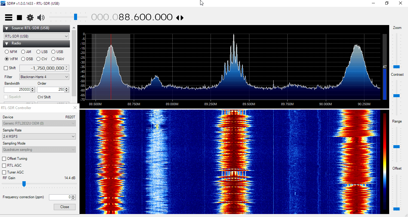
Hi, I bought a dongle last month with the FM filter. This is the result without filter
https://drive.google.com/open?id=0B7rjHOQUYb6zQVZ0UENDZ0RmdTQ
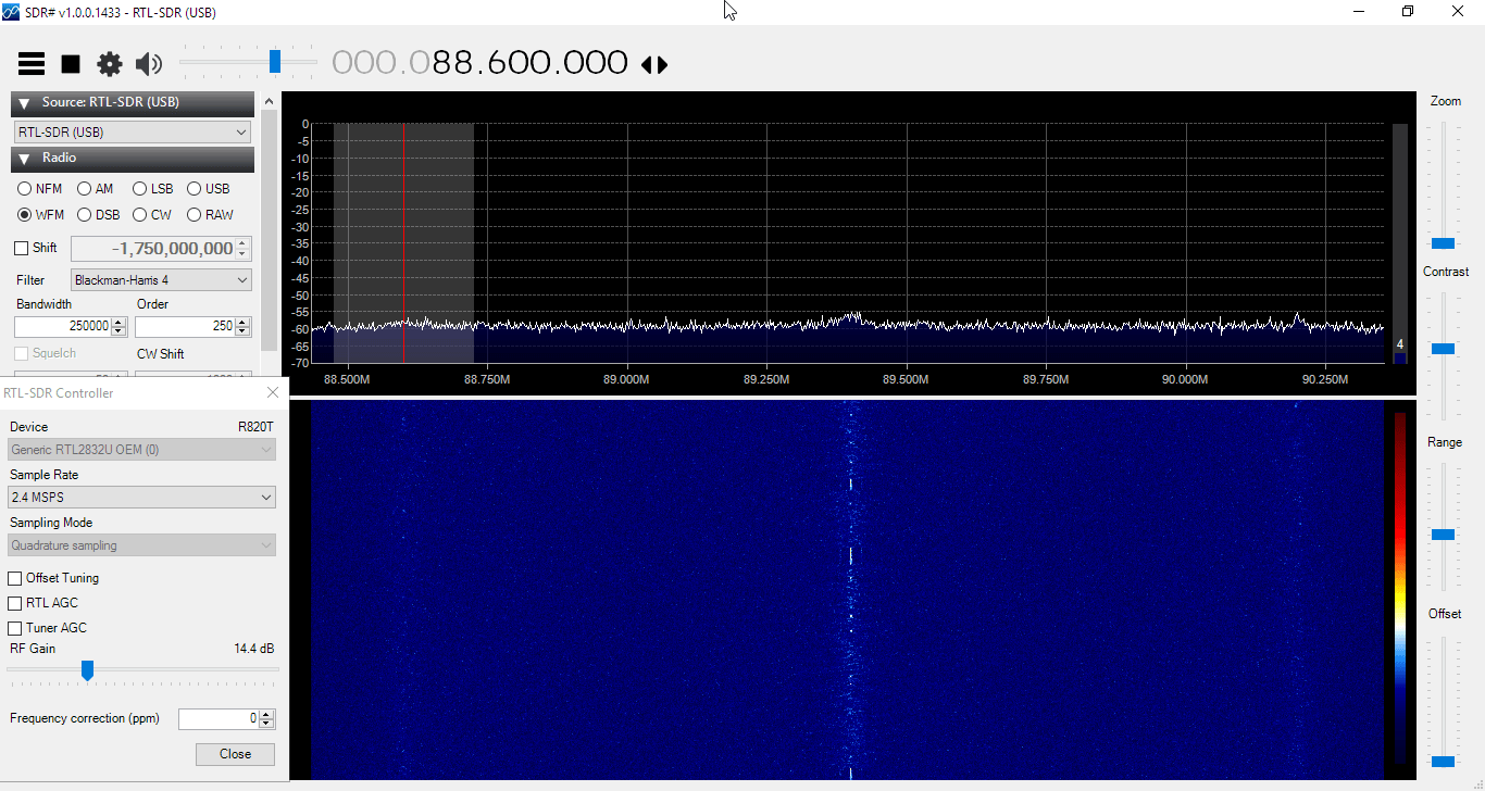
and this with the filter
https://drive.google.com/open?id=0B7rjHOQUYb6zS0Z4cHlJTklZREE
Virtually no difference. It’s normal? I would like to buy another dongle (exceptional product) and another filter, but if this is the result of the filter I’m very puzzled. Thank you.
Hi,
Your results are strange, indeed.
Either you receive very strong FM band signals, which means that a filter is not enough, or your filter does not work.
Check my web page on the subject: http://www.arrad38.fr/bidouilles/Notch_FM/Notch_FM.htm (Sorry, this is in French only).
You should get something as described in this PDF: http://www.arrad38.fr/bidouilles/Notch_FM/Notch%20FM%20BroadCast%2088-108%20MHz%20by%20F1JKY.pdf
Yet I take the most unfavorable case of my Notch FM filter.
A track, you may have bad welds on your filter, it might be worth trying to redo them to see if this improves your problem.
Good research.
PS: Excuse me for my appalling English … ;o(
Some questions:
Is the RF gain setting identical for both screenshots? Use manual gain and compare with filter on and off.
Can you also please increase the range slider to -70, and take screenshots again? In the “With filter” screenshot your noise floor is significantly lower, which is a good thing and indicates that the filter is working normally. In the “without filter” screenshot your noise floor is very high. My theory is that your signals are so strong that the dongle is significantly overloaded, so that makes the noise floor very high. When you add the filter, the BCFM signals are not as strong, and the dongle is no longer overloaded. Now the BCFM can come in clearer, and that is why the SNR is higher with the filter on. So the filter is working as it prevents your dongle from entering overload which is the whole point of it.
Also check, could you be getting interference entering through your USB cable? Check to see what results you get with the antenna disconnected.
Hello,
First of all thank you all for your interest.
1) The configuration of SDRSharp is exactly the same, the only difference is the presence of the filter.
2) New screenshots
with https://drive.google.com/open?id=0B7rjHOQUYb6zZVdQUUV1MURXMU0
without https://drive.google.com/open?id=0B7rjHOQUYb6zdTBSZldBVWtsTDg
3) No signals are detected without the antenna. If I touch the dongle with her hands appear stations as if there was the antenna!
4) However, with the filter, the FM station images over 108 MHz disappear.
Thank you
What is your gain at, because from the images it feels like you may have them turned up the the maximum, or else you live right next door to all the FM transmitters in the area.
Click on the “gear wheel” icon (“Configure Source”), move the dialogue box to say the bottom right hand corner and include the current gain settings in the screen shot.
Mea culpa…
The dongle was set with an exaggerated RF gain for an attempt to receive satellite weather.
No filter, 0 dB RF gain
https://drive.google.com/open?id=0B7rjHOQUYb6zSklSV056ODNzSlU
With filter
https://drive.google.com/open?id=0B7rjHOQUYb6zZXZkYWNkOS1CTFk
https://drive.google.com/open?id=0B7rjHOQUYb6zZkhhQkRRSlNVSzg
https://drive.google.com/open?id=0B7rjHOQUYb6zelNBOGtiM0Y5YjQ
https://drive.google.com/open?id=0B7rjHOQUYb6zUGFaWHFjQW5CRUE
I think the result is very interesting. Thanks to everyone and apologize for the disorder and … my English.
Yep, here you can see that the filter is working as expected. (I’d suggest turning OFF RTL AGC however).
The filter can only take the signals down about 50-60 dB. But with the gain turned all the way up your signals are stronger than that.
But regardless the filter did its job well enough with 50-60 dB attenuation of the BCFM band so that your receiver is no longer in overload even with the gain turned up. So you no longer see images over 108 MHz, and now your weather satellite signals should be able to come in better.
Please make dab filter 175 MHz-230MHz. Very very very strong carries.
the signals are so strong…
Works like a charme! TnX dudes!
I can’t build this for E15 inc shipping…!
I do need one for me plase let me have the cost including shipment to Italy .
Regards,
iw2fvo
Ambrogio
[email protected]
please make a DAB Stop Band Filter for Europe. 175 MHz-230MHz. Very strong carriers in europe.
mine perform very well.. i’m waiting for a variable 50 Ohm attenuator in the same form factor and a rf amplifier with variable gain and RF bypass fuction ( pass RF through the amplifier when switched off). the enclousure is very nice.
Janilab’s LNA does that.
How long does it take to get the FM band stop filter from China to say Windsor Ontario Canada?
We can’t really say for certain, because it depends on many things like how busy the air mail system is, the demand for flights, holidays, local customs delays, local post sorting delays etc. We can only really say between 1-4 weeks on average.
My FM Filter arrived by mail from China, and I put it on my Network Analyzer. Here is a sweep from 50Mhz to 150MHz. The performance is nothing like was advertised, and is barely useful. Looks to me like the filter was assembled incorrectly..
http://trevormarshall.com/temp/RTLSDR_FM_150MHz.png
Hmm looks wrong..are you sure your NA is calibrated properly? We tested several units on two calibrated NA’s and they both gave the same results as in the post. How does it perform on the actual radio?
We investigated this further and found that some low cost digital analyzers show an inaccurate result, very similar to what you showed. Inaccurate results are also shown on other brands of BCFM filters too. When tested on a higher end bench top network analyzer they show the true result, which gives results similar to what is shown in this post.
Our test digital N/A: https://www.rtl-sdr.com/wp-content/uploads/2016/11/digital.png
Our test bench top N/A: https://www.rtl-sdr.com/wp-content/uploads/2016/11/regular.png
Both tested on the same filter unit.
I believe the problem with the digital network analyzer is related to the bandwidth & overload. There is too much power in the result because the BCFM bandstop filter is only blocking a very small portion of the tested bandwidth. The digital N/A works fine on a bandpass filter because the total power is reduced a lot more, giving more accurate results.
Placing a ~370 MHz LPF in series with the BCFM filter to limit the N/A bandwidth of the digital N/A allows a more accurate result to be seen. https://www.rtl-sdr.com/wp-content/uploads/2016/11/digital-LPF.png
We also tested with a BG7TBL noise source and an Airspy, and without an attenuator or LPF the Airspy also did not give an accurate result, because the total input power was too high.
Will this stop the FM stations interference in HF ,UHF bands?
e.g when I tune at 145mhz onwards there are FM interference and also in sw lot of images from local FM stations.
Will this block these interference s in these bands?
Yes if you’re seeing FM images, then you need to filter out the FM band.
Will the FM Trap be available on Amazon soon? I want to order a couple as well as the new V3 batch 2 dongles.
Not for a few months more, at the moment just from China sorry.
Is there any “seamless integration” driver being worked on for sdr#? To turn on and off the bias tee as required for HF or not for people who use a spyverter in front of the rtl-sdr? (equivalent to the “use spyverter for HF” option on the airspy)
Okay we’ll work on getting something like this out by the end of the year hopefully.
Hello to all,
In first, I wanted to congratulate you for your work, I follow you for a long time and I must say that I am satisfied with your products, so much software that material.
However, I find funny that your filter Notch FM looks like to deceive themselves of it to my realization that is now available since quite a lot of time, either on the site of the ARRAD 38 (http://www.arrad38.fr/bidouilles/Notch_FM/Notch_FM.htm… in French only, sorry), either on the site of Makis SV1AFN (https://www.sv1afn.com/band_reject_88_110_mhz.html).
Personally, I get some results a little better in Notch with a Span Bande a few narrower, what can be interesting for people interested by the adjacent frequencies.
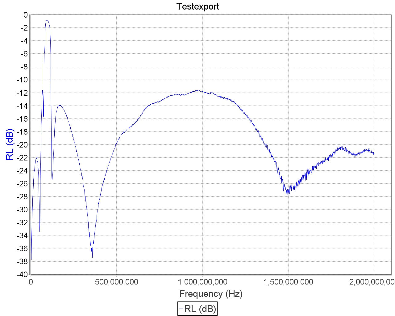
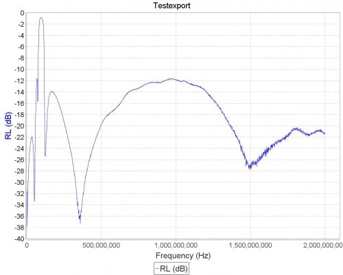
I give the measures of RL of my filter but I don’t see yours, it is a pity.
I hope that your users will understand the importance of the use of such a filter owing a key RTL-SDR.
Good continuation.
Thanks! I added a RL graph now on the first image slider. I’ve seen SV1AFN’s and your filters before and have recommended them to customers in the past. But many were unwilling or unable to assemble it in kit form, so we decided to sell a ready to go model. I see your filter has 3dB rolloff at about 112 MHz and SV1AFNs at 128 MHz. I think for a BCFM filter it is important to filter heavily up until 108 MHz to ensure no strong signals can get through and overload the SDR. This means that the lower airband will be cut off (though I think 108 – 118 is not that interesting for most people). For airband I think it is better to use a sharp bandpass filter instead.
The full coverage of the FM band is the reason why i purchased this filter. This is a FM trap and it makes no sense to me and to my wallet if it doesn’t filter all the stations at its best. I remain curious how these filters can be fine tuned (i mean in the project) if you have to rely only on standard values of the smd components.
Dear Max,
As I said, it’s a compromise to be in this kind of design.
You can not have 75dB rejection (60dB or for the release of our friends at RTL-SDR) over the entire FM band from 88 to 108MHz without much loss on adjacent frequencies … which can be a problem for people who want to listen to these bands with minimal loss of efficiency.
Obtain such performance is virtually impossible for amateur means, with a small size and at an acceptable cost.
Everything is a matter of compromise depending on your usage, but the performance already achieved, are already very good.
To answer your question, I have long sorted components that I use for my filter version Notch and I can assure you that these are not standard components, with basic features … and without wishing to speak for them, I think it is the same for our friends in the RTL-SDR team.
Best Regard’s.
Dear Admin,
It is effectively a choice and the two ways to see the things defend themselves.
Personally, I preferred to lose 3dB of attenuation on the extremities of the FM bande to encourage the adjacent professional bande monitoring … because there are more people than one believes persons concerned for example by the monitoring of the airband.
Thank you for the addition of the measure of RL, it confirms that our filters are very near.
I think that you could improve a little again the reject of your Notch filter, because I manage to get about 15dB of better between 91 to 102MHz.
My objective on the realization of my filter was to make to participate, by a mechanical construction minimum, people interested by the performances of this FM filter because I find that the radio hams (notably) achieves their material less and less, what is unfortunate because one loses our knowledge to make.
I wanted, with my means, motivated all over again the personal realization … my goal not being to win money with it, but well to help while achieving the part the more to complicate the realization to make easily he accessible to all.
What interests me is the side helps associative of our hobby, I let the commercial and financial part of this project to Makis SV1AFN to that I gave all right of exploitation of my realization for its own account.
Your case with alot certainly satisfy anyone wanting a ready to use product and it fits well with your business direction … it’s perfect like that.
Good continuation to all the team and excuse me for my very bad English !
Best Regard’s.
Need a filter for pagers too.
These filters filter frequencies, not pagers 🙂
What frequency? I think there are several pager frequencies. Maybe try a coax notch filter.
Now if only they had a filter to block out the national weather service. That crap comes in on all my radios even without an antenna.
What should that be? I never heard of that.
I ordered this filter, it will be very usefull in my area.
Will you plan to make a DAB band stop filter too ?
Problems with band III I assume? What country are you in?
I’m in Paris (France)
yes, please make a DAB Stop Band Filter for Europe. 175 MHz-230MHz. Very strong carriers in europe.
My SDR was shipped on 27th Sept and this week I will be receiving it. Which model I will get? V3 batch 1 or 2
Batch 1, batch 2 is not shipping yet.
:(:(:(
When does shipping start for batch 2 ? If i order today, will i get a batch 2 ?
Yes B2 is shipping now.
for a single nearby FM, try using a quarter wave shorted stub. just use a bnc (or your favorite) T, and 300/Mhz /4 will give you the wavelength in meters + velocity factor makeup of the coax you’re using. short the center to the braid and attach to the T inline with the antenna line. consider using the noise generator on the hamitup to tune the length. trombone sections also work well.
handy for FM, not feasible for AM! 🙂
You may also call the station and ask for engineering. tell them what you’re doing and ask if he has any traps you can have. most people will be happy to help.
Looks quite good.. so I ordered one. Now that the V3 does shortwave.. How about a high pass filter for the Medium Wave band ? It’s stations can be a nuisance in the Mhz above it.
Thanks. We’ll look at the possibility of making a BCAM blocking filter too.
Yes please. Spurious signals from local AM stations are my biggest problem
Yes, please.
Missed batch 2 by a few days. grrrr
So i see its not good for Airband. I use an AOR ABF128SMA who works perfectly (for Airband).
Yes if you’re interested in 108 – 118 air band then this is no good. It’s not really possible to alleviate this without using more components, or significantly sacrificing attenuation at 108 and lower.
But from about 120ish MHz the IL is less than 4dB, which is less than the 4dB pass band IL of the AOR filter. So it should be okay for the 118(120) – 137 MHz voice portion of the air band. Of course the AOR is a band pass, and this is a band stop so this won’t help if your air band interference is not coming from the BCFM band.
Is is possible to have the new V3 batch tweaks explained / published for at home retrofit on a V3 first batch?
You’ll need good SMD skills for most changes: Add 100-220uF to the 3.3v line (can be easily added on the 3.3v and GND pins on the breakout pads). RF2 -> 0ZCM0020FF2G fuse (LDO protection), C24 -> 2.2uF (improves bias tee performance on HF frequencies), C14 -> 330pF (reduces side band noise on very strong signals) (C14 is next to the R820T2 chip, stencil is a bit hard to read but it goes R9, C30, R8, C14, C11, C4, L2.
Great ! Thank you!
Really unfair comparison in the plots
If you click on the second photo link you’ll see a plot that goes out to 2GHz, which is an apples to apples comparison.
Understand where you’re coming from – I thought the same thing at first.
I had to look at the graphs carefully, but there are two with the same axes and scale. And the $5 FM band-stop does perform very poorly, by comparison. I think that it was not having a side by side comparison that confused me.
The last image slider has a comparison you can see by clicking between the two images.
It looks excellent! Big attenuation and very sharp; not wasting too much of the adiacent bands. In the cart!