SDRPlay RSP2 Release Announcement and Review
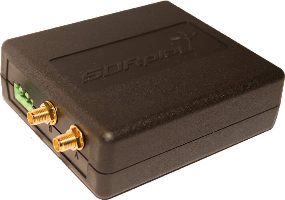
Today SDRplay have just released their newest software defined radio – the Radio Spectrum Processor 2 (RSP2) which is the successor of the RSP1. The RSP2 costs $169.95 USD, and the older RSP1 is still for sale at $129.95 USD. There is also the “RSP2pro” model which is an RSP2 in a metal enclosure, and this sells for $192.95 USD.
The RSP2 has nearly the same base specifications as the RSP1 (12 bit ADC, 10 MHz bandwidth, 10 kHz – 2 GHz range), but now comes with additional features and enhancements such as a software switchable BCFM and BCAM notch filter, TCXO, multiple antenna ports, HF optimized Hi-Z antenna port, clock in and out ports, better shielding and can also now tune down to 1 kHz.
It is available for purchase at sdrplay.com/rsp2 (Worldwide), HamRadioOutlet.com (USA) and ML&S (UK).
The announcement reads:
SDRplay Limited has today announced the launch of a second Software Defined Radio product – the RSP2.
Building on the popularity of our first product, the RSP1, we have now launched the RSP2. The RSP2 delivers a significant number of additional features which result in a higher spec for specialist amateur radio users as well as benefits for additional scientific, educational and industrial SDR applications.
Here are the main additional features of the RSP2:
- 10 built in front-end pre-selection filters, with substantially enhanced selectivity
- Frequency coverage extended down to 1 KHz
- Software selectable variable gain Low Noise Preamplifier
- 2 x SMA Software Selectable 50Ω RF ports (1.5 MHz – 2 GHz)
- 1 x High Impedance RF port (1 kHz – 30 MHz)
- Built in software selectable MW /FM notch filters
- Highly stable 0.5PPM TCXO trimmable to 0.01PPM
- 24MHz Reference clock input / output connections
- 4.7V Bias-T option (on one of the software selectable antenna inputs)
- RF screening within a strong plastic case for the standard RSP2
- A Rugged metal box version – the ‘RSP2pro’
When used together SDRplay’s own SDRuno software, the RSP2 becomes a high performance SDR platform. The benefits of using the RSP2 with SDRuno include:
- Highly integrated native support for the RSP2 professional grade software based upon class leading ‘Studio 1’, free of charge
- Calibrated S-Meter including support for IARU S-Meter Standard
- Calibrated RF Power Meter with in excess of 100 dB of usable range
- Best in class audio quality
Currently the RSP2 requires the use of SDRuno software, but in the coming weeks we plan to provide support for HDSDR, Gnu Radio, CubicSDR and we are working with Simon Brown to get support within SDR Console.
We believe that the RSP1 will continue to prove very popular as the lowest cost 12-bit SDR for general applications such as Short Wave Listening or for use as a panadapter and we pleased that we can now offer more choice to the growing community of RSP users.
The RSP2 is expected to retail at approximately £130 (excluding taxes) or $169 (excluding taxes)
For more information visit our website on www.sdrplay.com
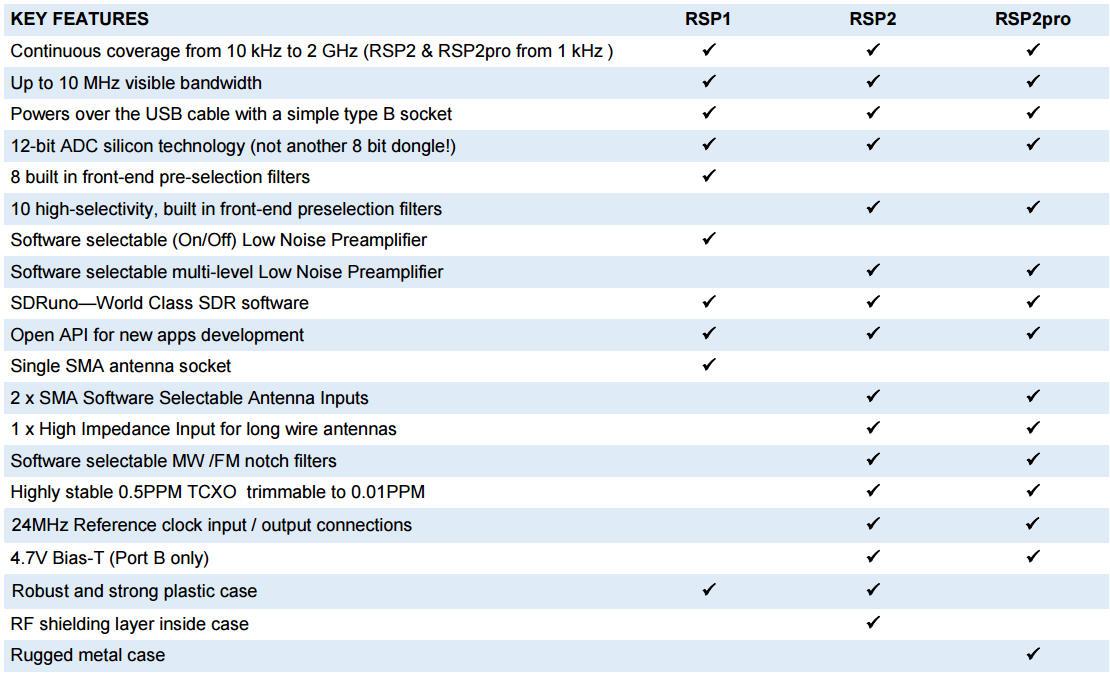
The table below shows a comparison of the RSP1, RSP2 and RSP2pro. A datasheet can be found on SDRplay’s new RSP2 webpage.
SDRplay RSP2 Review
Two other reviews have already come out, one from swling.com and one from NN4F.com.
Thanks to the generosity of the SDRplay team we were fortunate enough to receive an early pre-production review model of the standard (not pro) RSP2 unit. The unit arrived a few days ago, and here we give it an initial review. In a previous review we did a comparison of the Airspy SDR, SDRplay RSP1 and HackRF. We found that the RSP1 and Airspy had similar overall performance, but that the Airspy would be better for those people who needed high dynamic range performance in strong signal environments, and that the SDRplay RSP1 would be best for people who wanted a low cost all-in-one unit with performance better than an RTL-SDR.
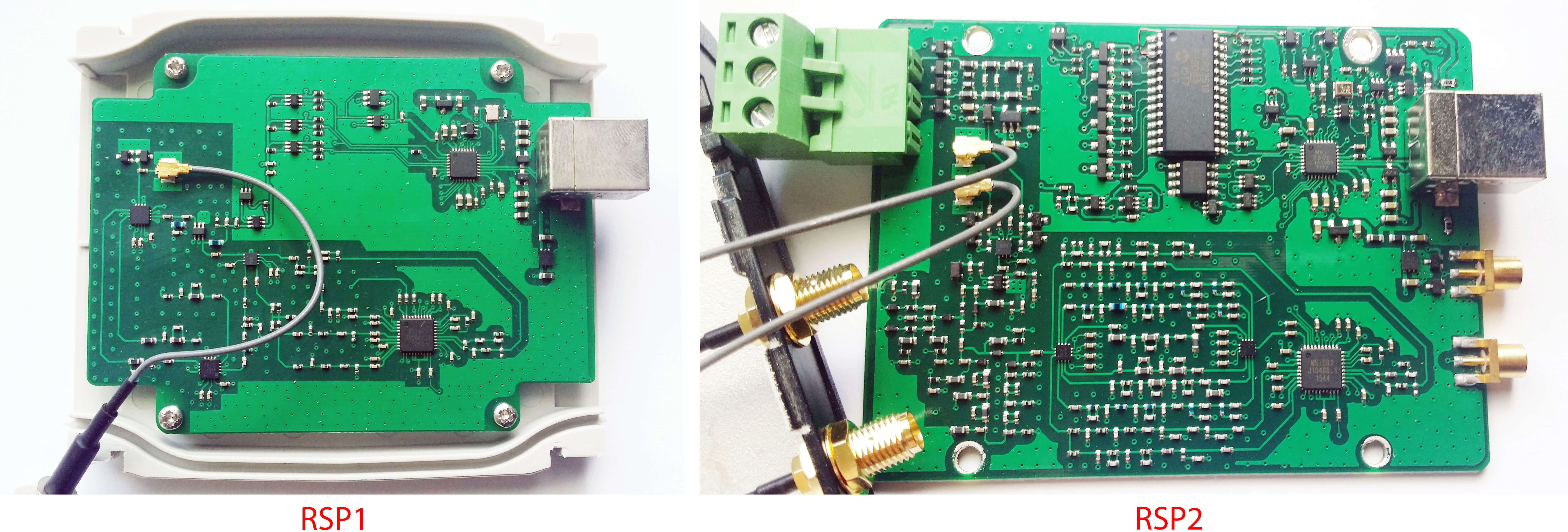
The Inside
We decided to take a look inside and see how much the PCB has changed from the RSP1 to the RSP2. Judging from the two photos we can see that there is quite a significant increase in the number of components used. What was once a sparse PCB is now populated much more heavily with additional filter banks and several new switches. However, the core design of the RSP2 remains similar to the RSP1. The RSP2 uses the same Mirics MSi001 tuner chip and MSi2500 ADC chips.
The standard plastic enclosure is also now spray painted on the inside with conductive metal paint which helps by acting as a Faraday cage. This prevents interference from getting through and should be almost as good as a metal enclosure.
The conductive paint seems to be working well, as in our tests the RSP2 does not receive any signals with the antenna disconnected, whereas the RSP1 does weakly receive some very strong pager signals.

Continue reading for the rest of our review
New Antenna Ports
The RSP1 was simple and had one RF port for the antenna. In comparison the RSP2 now has three antenna ports and two clock ports.
Ports A & B are standard 50 Ohm SMA female ports, with port A tunable from 10 kHz – 2 GHz, and port B tunable from 1.5 MHz – 2 GHz. Port B can also be used with the 4.7V bias tee. Having two antenna ports is useful as this means that switching between two different antennas made for different bands is made much easier.
The Hi-Z port operates from 10 kHz – 30 MHz and is used for high impedance HF antennas such as long/random wires and loop antennas. More on this port later in the review.
There are also now two clock ports available. One “in” port and one “out” port. The “in” port allows you to connect a highly stable external 24 MHz clock reference if desired. The “out” port allows you to connect two RSPs together for experiments that require clock sharing. Hopefully we’ll start to see coherent receiver projects with the RSP2, such as passive radar and direction finding experiments.
TCXO (Temperature Compensated Crystal Oscillator)
The RSP2 comes with a very stable 0.5 PPM TCXO. The RSP1 did not use a TCXO and this was one of the most requested upgrades. Use of a TCXO means that you won’t have to do any initial calibration to get the frequencies to show up where they should be and it also means that the frequency of signals on the display won’t drift over time as the ambient and internal PCB temperature changes. This makes the RSP2 much more usable at L-band frequencies where the apparent drift is much larger.
In our tests we found that the frequency calibration was spot on without the need for any adjustments, and no drift was noticeable over a period of time. If you want to calibrate the TCXO perfectly, SDRuno has an autocalibrate mode now. Simply select the “SAM” mode, tune to an known accurate signal, then click on the “Autocal” button in the RX settings menu.
New Preselectors
The RSP2 has two additional preselectors which appear to be aimed at improving reception on the milsat bands around 250 MHz, as well as signals between 300 – 380 MHz. Previously we’d seen reports that the RSP1 has problems with milsat reception, so this may be a fix for that.
It’s not mentioned in their release documents, but we’ve heard that the preselectors have also been tweaked to be much tighter, meaning less roll off, and so they should give better rejection of out of band signals. They have probably increased the filter order which means more components. This may be partially why the PCB looks to be so much more filled out.
| RSP2 Switched Preselectors | RSP1 Switched Preselectors |
|
|
Bias Tee
The RSP2 includes a 4.7V bias tee on the SMA-B port. This is very useful for powering remote low noise amplifiers. Generally, you’ll want to place an LNA close to an antenna placed up high, say on the roof. The LNA will then help overcome any losses that come from using coax cable.
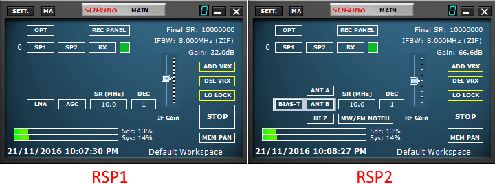
The problem is that it may be difficult to find a power source for an LNA when it is in an inaccessible location like up on a mast or on the roof. The solution is to use a bias tee, which allows you to inject DC power onto the coax cable. The coax cable itself can then be used to power the LNA. To activate the bias tee simply click on the “BIAS-T” button in the Main SDRuno window.
We tested the RSP2’s bias tee with SDRuno and found that it worked as expected. We didn’t see a current limit rating for the bias tee, but it seems to work just fine with a PGA-103 based LNA that draws about 100 mA of power. We also tested the bias tee together with the Outernet LNA and we were able to receive L-band signals with no trouble. Finally it was also tested with a Chirhiro Miniwhip HF active antenna, and the bias tee powered it up with no problems.
Note that just like with other SDRs that have bias tees, if you use a long USB cable the voltage you get out might be lower than the specified 4.7V. With a long 10m USB cable the RSP2 put out 4.2V, which was still sufficient to power all the LNA and devices.
FM and MW Notch Filter
One problem with the RSP1 was that it seemed susceptible to overloading and non-linear mixing from broadcast FM (BCFM) stations. This could cause desensitization and images of BCFM signals to appear on top of other signals. This happens because BCFM stations tend to be local and thus extremely strong in many locations which can cause the RSP1 to overload. The solution is to filter it out, or to somehow improve the dynamic range of the receiver with higher bit size ADCs or other design improvements. (If you don’t understand overload think of someone trying to talk to you in a noisy bar with a live band. The loud sounds from the band will make you unable to listen to your friends voice. The same happens with radio – the strong BCFM signals make it difficult to hear weaker stations)
The RSP1 and RSP2 use an array of automatically switched band pass filters to reduce interference and overloading problems. The filters near the BCFM band are 30 – 60 MHz, 60 – 120 MHz, and 120 – 250 MHz. Signals between 60 – 120 MHz are most likely to experience problems because the BCFM band is between 88 – 108 MHz, and so between 60 – 120 MHz there will be no reduction of the BCFM signal strength. Signals between 30 – 60 MHz and 120 – 250 MHz can also experience problems because the filters are not perfectly rectangular, meaning that attenuation of the BCFM band may not be strong enough to prevent overload.
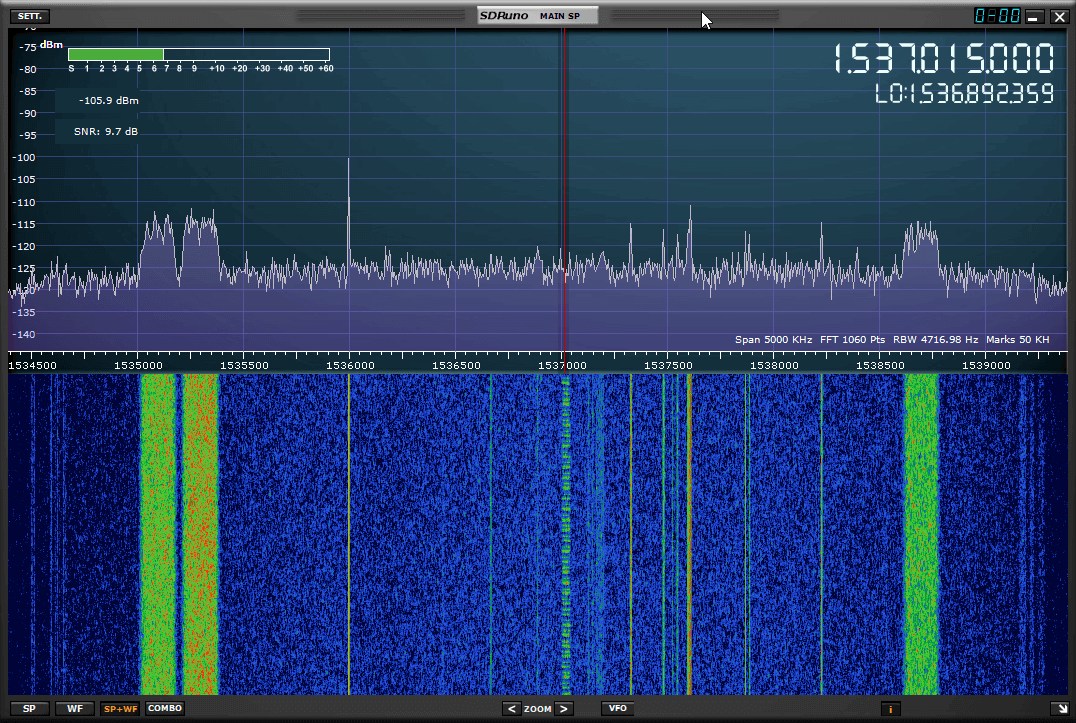
To help fix any problems related to BCFM overload the RSP2 has included a software switchable BCFM band stop filter. This does the same job as the BCFM bandstop filter that we sell, but it is built in to the RSP2 itself. This filter attenuates (reduces) the signal strength in the BCFM band (between 88 – 108 MHz), thus preventing the signals from being too strong and overloading the RSP2. The filter can be turned on and off easily by clicking on the “MW/FM Notch” button from within the main control screen in SDRuno. We did notice some small insertion losses of about 1-2 dB’s on other signals when this filter was turned on, but it is certainly worth it to use if you are experiencing BCFM overload. If you are not experiencing overload then it is best to keep this off.
The same button also turns on a MW (AM broadcast band (BCAM)) filter when SDRuno is tuned to 30 MHz or lower. Again the same problem as with BCFM can occur on HF. Signals from the often local BCAM band are so strong and this can cause the receiver to overload. The MW notch filter attenuates this band significantly, eliminating any overload problems caused by the BCAM band. The BCAM notch filter is only available in the SMA-A and SMA-B ports and cannot be used on the Hi-Z port.
See the image below for a comparison with the notch turned off and on.


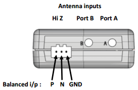
High Impedance (Z) Input
One useful addition to the RSP2 is the High Z input port. This input has an impedance of 1 kOhm and is only active when the unit is tuned to frequencies between 1 kHz – 30 MHz. This port is now intended to be the main port for connecting to HF antennas.
Normally radio input impedance is 50 Ohms, and the antenna should also be designed and matched to be as close to 50 Ohms for the frequencies you are interested in. Normally if an antenna has a high impedance characteristic an impedance transformer is used to reduce it to something closer to the typical 50 Ohms.
The idea with the High-Z input port is that these high impedance antennas can be connected directly to the radio, eliminating the need for any impedance transformers. Good impedance matching typically results in stronger signals and less noise.
Examples of high-Z antennas include the simple “random wire” or “long wire” antenna and balanced loop antennas. Random wire antennas should be connected to the “P” (leftmost) input on the high-z connector with the “N” (middle) input connected to the GND (rightmost) input.
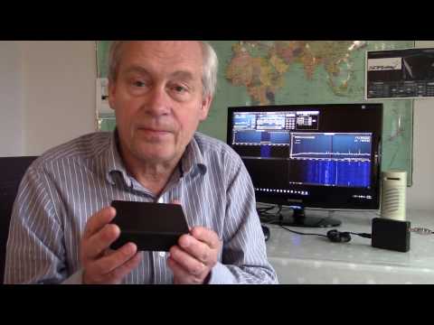
The video below explains the ports including the High-Z port in more details.
We tested the Hi-Z port and had no trouble getting good HF reception with a simple random wire antenna. It definitely did seem to give better reception compared to the SMA ports. However, we wish that the MW bandstop filter had also been implemented for this port.
See the image below for a test. Both tests were tuned for maximum SNR. The Hi-Z port image shows higher SNR and less noise.


We asked SDRplay for some more information about this port and they wrote:
Regarding HF usage: Ports A and B are intended as general purpose RF ports, but the Hi-Z port is really intended as the prime port for HF and below and has been optimised as such. This is one of the major changes in thinking from the RSP1. The reasoning here is that you will never get a single antenna that gives optimised performance from VLF to UHF and so the majority of people will tend to use separate antennas for HF and VHF/UHF. We chose a 1 K ohm impedance for this port, to simplify the connection to a random wire antenna which is the antenna of choice for HF for many of our customers and is also a good choice for frequencies below 1 MHz. Because of the long wavelengths involved at HF, this port also works well for 50 ohm antennas as long as the feed cable is not excessively long, but if someone really did want to us a very long feed cable (say 30m for example), you could simply reverse a 9:1 balun and use it between the Hi-Z input and the end of the feed cable and you would get a perfectly adequate match to 50 ohms for this purpose. When operating below 1 MHz (down to VLF), though, the direct connection will work best, even with a 50 ohm feed as the high impedance termination will deliver the highest terminal voltage at the input to the RSP2 and reflections will really not be a problem because the wavelength is so long.
New Built in LNA’s
We asked SDRplay for more information about the new LNA’s they have used. They wrote:
On the RSP1, the LNA had only 2 states, on/off. In reality it is not strictly true to say the LNA was ever off, but instead it has a fixed 24 dB gain step in HF and VHF bands. This gave the user only two possible settings in which to trade off noise figure for improved intermodulation performance. With the RSP2, we have added many more gain states for the LNA (5 on the Hi-Z port and up to 9 on ports A and B). Each state has a different trade-off between noise figure and signal handling and so this gives the user a lot more flexibility in handling a wider range of signal reception conditions. As a consequence the slider that you now see in the Main Panel adjusts the LNA gain only. The IF gain is controlled automatically and only serves to ensure that the ADCs do not overload.
Software
SDRuno is the official software for the RSP1 and RSP2 and is free of charge. Operation of SDRuno on both units is similar, but there are several new buttons available for the RSP2 which can be used to select between the three antenna ports, and turn on or off the notch filter.
At the moment the RSP2 is only compatible with SDRuno but the SDRplay team write that they are working on support for HDSDR, GNU Radio, Cubic SDR and SDR-Console.
SDRplay also have RSP compatible versions of dump1090 available on their website. The RSP2 should be able to perform very well on ADS-B reception now with its bias tee and a remote LNA.
Teething or Actual Problems?
When testing the RSP2 we ran into a few problems. Some of these we’re not sure if they’re actual design faults, or maybe a software bug, or perhaps something was wrong with our unit since we received a pre-production unit. We don’t want to speculate so we’ve informed SDRplay of most of these issues and they are looking into it and we’ll update this part of the post as soon as we get more information.
Notch filter problems
While testing the notch filter we encountered some problems that don’t really make sense. The notch filter appears to work perfectly fine while tuned to or very near 88 – 108 MHz, however, when tuned further away it appears to not work. For example we tuned to 200 MHz and saw heavy BCFM imaging, so we turned the notch filter on. But with the notch on we saw no reduction in image signal strength, in fact the images seemed to get even stronger with the notch turned on. Adding in an external BCFM bandstop filter near the RSP2 completely removed the images. No preamps were used and the antenna was a discone.
To be fair we did test in an environment with very strong BCFM signals, but this should be exactly the environment that the notch filter is supposed to help with. Hopefully this is just a glitch in the software not turning the notch on properly, or perhaps a fault in our pre-production hardware as this behavior doesn’t really make sense for the notch filter.
BCFM Interference on HF
The SMA-A and SMA-B ports appear to have BCFM interference problems on HF. When using a discone to receive the AM broadcast band or other HF frequencies we saw lots of BCFM interference. The same interference does not appear on the RSP1, or if we use the Hi-Z ports. The SDRplay team have indicated that the Hi-Z port is now recommended for HF use, but it is strange that the SMA ports are not working as well as on the RSP1.
The discone is not really a HF antenna, but we do sometimes use it for listening to broadcast AM.
Leakage between Port-A and Port-B
There appears to be some signal leakage between the two SMA ports. For example we connected an antenna to the SMA-B port, and selected the SMA-A port. Even with SMA-A selected and no antenna connected, we received strong BCFM signals. Disconnecting the antenna from the SMA-B port made the signals disappear. This is probably not an issue for most people, but if you have really strong BCFM or other signals leaking through the other antenna it might mean that you will still need to manually disconnect it to avoid possible interference.
Software Bugs
We used SDRuno V.11. The SDRuno software sometimes seems to get confused with the gain settings. Sometimes it seems like the RSP2 is not receiving anything, but simply moving the gain slider up and down, then back to where it was before usually brings the signals back. Sometimes instead switching back and forth between ports A & B fixed it.
UPDATE 24/11/2016: Regarding the issues SDRplay responded
..we have been looking at this in some detail and we do believe that we understand what you are seeing. The RSP2 and the RSP1 before it uses a switched filter matrix in front of the MSi001 to provide front end selectivity. With the RSP1, the front end band-pass response of these filters were fairly gentle and what many users found was that when operating in the air-band, 2m or 4m bands, the front end filters gave insufficient rejection (if the user was operating in an area with very strong BCFM signals) to allow the user to operate the unit with the LNA ‘on’ and thus achieve the best possible sensitivity. This was one of the design constraints of the RSP1 that we were aiming to address with the RSP2. As well as significantly improving the stop rejection of the band-pass filters, we decided to add an FM notch filter as there is a limitation to what rejection of BCFM signals that we can realistically achieve for the lower end of the Air Band when using a band-pass response.
To make these filters software controllable, we have to use the already mentioned front end switching network and necessarily this means the use of semiconductor RF switching elements such as FETs and diodes. What you have observed at 200 MHz is second harmonics being generated within this switching network, which is why you have seen that the notch filter has no effect on them, but does have a very beneficial effect in the Air Band. In other words, it is not the MSi001 that is generating these images, but given the very large BCFM signals in your area, you are seeing harmonics being generated in front of the notch filter which appear as low level images.
Whenever you are operating in an area of high RF interference, you would always ideally place your pre-selection filters right at the antenna. To avoid the effect that you have observed completely, it would be necessary to go to a completely mechanical switching arrangement such as swapping cables or using RF mechanical relays. Software Defined Radios always involve a degree of compromise as there is always a trade-off between size, cost and performance. The key, we believe is to maintain flexibility so that users retain as many options as possible for dealing with the various situations that confront them. In this case, the option to swap cables and use an external notch filter remains in the cases where the internally switched notch response doesn’t provide sufficient protection.
We will do a little bit more assessment of the differences in the pre-production design that we sent you and the final production design. As I have already mentioned, we did tweak the input match for the production units to improve the intermodulation performance on ports A and B and so it is possible that this may have some bearing on the levels of harmonics that you are seeing, if not the effect in itself. It will take us a little bit of time, but if we find the production units are different in this regard, we will ship you out an new unit so that you can compare.
Conclusions
The RSP2 is an excellent upgrade to the RSP1 however the core technology of the RSP2 has not changed from the RSP1 so this is more of an evolution of the RSP1 rather than a totally new product. The evolution of the RSP1 to RSP2 does implement several enhancements and new features that will make using the RSP2 much more enjoyable.
Below is a review of the new features and enhancements we’ve found:
- Many of the issues that some SDRplay users experienced with overloading should be significantly reduced in the RSP2 thanks to the BCFM and BCAM notch filters and the additional band pass filters.
- Users can now use the bias tee to power remote LNA’s like the LNA4ALL in order to overcome coax losses.
- The High-Z port provides an easy way to get started on HF with decent performance with a simple random/long wire antenna.
- The change to a TCXO increases frequency stability and now brings it in line with most other SDRs in this price range.
- The three antenna ports allow you to easily switch between antennas designed for different bands.
- Coherent radio experiments are now possible with the CLK IN and CLK OUT ports.
There do seem to be a few issues that we’ve encountered, but we are hopeful that these are mainly issues with our pre-production unit or software problems. We’ll update this post as soon as we receive word from SDRplay.


Which model is recommended for P25 P1/2 and /or DMR reception ? Also which software is suggested ? Thanks.
I am so looking forward to buying the RSP2. In my case, I am running a Mac (OSX 10.6), and equally enjoy Ham/Shortwave and VHF/UHF monitoring.
There are lots of applications out there that will handle the former by simply selecting a frequency and listening. There are few choices which actually work as a scanner where you have a bank of frequencies and the instant one becomes active, it is selected for listening, then returns to scanning when inactive.
For Mac users, there is only one option – SdrDx. This is a very beautiful and functional free application, but is not currently supporting RSP2 or even RSP1. The author reports that there are currently over 10,000 Mac users which have started his application within the last 30 days. It seems like you have a lot of potential customers (like me) who are eagerly awaiting a quality SDR receiver so that we can upgrade from our 8-bit dongles.
Please contact the author (Ben) and work out a pairing of these two great products and support for Mac users. You have an application writer who would be enthusiastic about adding your great hardware to his supported list. This is the perfect option for you to bring in the Mac community with a fantastic hardware/software pairing.
http://fyngyrz.com/?p=915
Eeek @ the update. The stronger your signals, the less effective is the filtering.
no driver for sdr#…
That’s because support for ExtIO was removed from SDR#. Here’s a thread that talks about it:
Obviously there are other options including SDRUno, SDR console, etc.
Wow, I *just* got my RSP1 in the mail the day before the announcement. The box is not even opened yet. I had no idea a new one was in the works.
Thing is, with the price being structured as it is, I am still happy with the purchase – so good job with the pricing! If I find I’m plagued with any of the problems model 2 solves, I’ll re-gift it and upgrade. Sometimes getting technology just off the cutting edge is good.
pre-announcing can lead to the “Osborne effect” and you are either stuck with old stock that you can not easily shift, or the company could go bankrupt when new sales drop to zero.
https://en.wikipedia.org/wiki/Osborne_effect
I owned an SDRPlay1 and after waiting 6 months for either recompiled drivers for glibc or an open source driver, got rid of the device. I couldn’t use it on Centos/RHEL 6 due to this lack
I never had luck having the RSP working on Debian either. Very poor software support. Sold after 2 weeks.
SDRplay listened, and added features.
“Knowledgeable pro and power users” as the coward without name or accountability put it, are far and few.
As a community loving radio, I think we should embrace the fact that one more affordable, high performance radio is now available.
Amen Akos. Even us “pros” who are used to working with equipment costing many times more than RSP2 are excited by the additional capabilities. SDRPlay listened and appears to have delivered. Personally and professionally, I place far more value on support and *attitude* than a performance difference of a few dB between competing products. This latest update just seals the deal on my next SDR purchase. The guys and the volunteers on social media from SDRPlay are knowledgeable, professional, and patient. That’s why I will readily send them my hard earned money.
HAHA nice one. Shouting the RSP is what professionals were waiting for is a funny but it just makes you look like another radio hobbyist trying to look cool.
Seriously, SDRPlay is far, faaaaaaar away from the 120dB of blocking dynamic range required in heavy duty radios used by *actual* professionals in dependable systems. These are not “a few dB”s, these are a few *dozens* of fu*ing valuable decibels. The difference between copy and no copy. Such compromises can only be tolerated in an amateur context, not professionally.
I can only see most of the work that has been done in RSP2 is “band aids” to push the saturation limit of the analog front-end “a few dB” higher when real antennas are plugged in and I am very skeptical about their actual utility. I want to seen an actual technical review and less fanboism. If it improves the RF performance, I’m sold. If not, meh.
Bryan, I’m flattered that you would take the time out of your busy schedule to engage in personal attacks. I consider it a badge of honor. You have just confirmed my purchasing decision is the correct one. Thank you.
Perhaps I should have explained myself better. As a *professional*, I get to select and work with equipment costing close to a thousand times more than the RSP. Few of us at a personal level can afford that kind of equipment. However, the RTL-SDR and RSP are inexpensive enough to play around with and allow one to prototype new ideas on both a professional and hobbyist level without incurring a significant amount of expense.
Ultimately the project requirements will determine whether you build, buy, or do something in between. These inexpensive SDRs, especially the RSP and RTL-SDR, are perfect for prototyping in an environmentally controlled lab or at home on a desk. They are just plain fun. However, they are not ruggedized and are therefore ill-suited for long-term use under extreme environmental including RF conditions. But if that’s not a requirement, then you don’t worry about it.
I love both RTL-SDR and SDRPlay products because I appreciate and respect their expertise, work ethic, and support. That really is the secret to success as explained by a farmer friend of mine just this past week:
1) Have a bit of talent/expertise
2) Work hard
3) Don’t be a jerk
.
“We chose a 1 K ohm impedance for this port, to simplify the connection to a random wire antenna which is the antenna of choice for HF for many of our customers and is also a good choice for frequencies below 1 MHz. Because of the long wavelengths involved at HF, this port also works well for 50 ohm antennas as long as the feed cable is not excessively long, but if someone really did want to us a very long feed cable (say 30m for example), you could simply reverse a 9:1 balun and use it between the Hi-Z input and the end of the feed cable and you would get a perfectly adequate match to 50 ohms for this purpose.”
I don’t understand this entirely.
Why does a 1 kOhm port work well for 50 Ohm antennas as long as the feed cable is not excessively long? And why should you connect a 50 Ohm antenna with an asymmetric feedline connect to a Hi-Z entry and not to the 50 Ohm SMA?
Why would a 1:9 unun in reverse (1 to coax – 9 to Hi-Z terminal) work well when the feed cable is very long? And why should this be better than connecting the feedline to the 50 Ohm SMA input?
I try hard to understand everything, something with less succes, so thank you for your help.
That’s what you get when some company is focusing on the noisy crap feedback they get from social media crowd douchebags where the loudest noob jerk gets the most attention, instead of listening to knowledgeable pro and power users among their customers who have real world demands. It may be true that most of the SDRplay users are wrapping random wires around their trailers to listen to Brother Stair, the majority of people who have a life, hams and radio enthusiasts may have different views on what they need. More specific, people who use for example a Wellbrook loop like me might get pissed off about the high impedance input for VLF and the BC band and never buy this thing. Since when is a random wire a good choice for VLF anyway??? I think they have been told ages ago that their input filters don’t always switch reliably (which may be the same bug mentiond in this preview ) and if they’re not getting this sorted out and port that bug to a the new device its probably not even worth considering. More than anything that thing has yet to prove that VHF and UHF is not a tacked on afterthought worthless sales pitch anymore.
Hi know what your talking about , I have always had the feelings that when it comes to antennas it a practice in the black arts . I know that when you look at old ham receivers you find that the antenna input is 600 OHM .
Notwithstanding the trolling comment above, I think I kind of understand what that quote means: at very short lengths, a transmission line won’t make a major amount of loss in receive-only applications even at high mis-matches–the same theory applies to transmitting to an unmatched antenna through some feedline via a transmatch / antenna tuner, but the losses are not as big a deal for receiving. However, at some length the line losses WILL get excessive *AND* the transmission line itself will become rather reactive. It’s worth noting here that 1000 KHz is 300 meters wavelength and a tenth of that is–tada!–30 meters. (1/10 wavelength an old rule of thumb when anything starts appearing significantly at a certain RF frequency: mag loops 0.1 to 0.15 wavelength, the holes in your microwave door and the old C-band sat dishes are less than 1/10th wave diameter, etc.)
Admittedly this is an educated guess, but it seems to fit, IMHO. But, yes, much of antenna design remains black art as well: regarding mag loops, people still can’t agree how efficient they are or what the best way to couple to them is (using transformer / loop coupling is just the most convenient, not necessarily best).
Replying to myself: DOH!!! 1 KHz/kc is 300 KILOmeters! 1 MHz/Mc is 300 meters. Ugh.
Oh the plus side, got my RSP2 the day after it arrived at my local HRO. Been sick, though, so I haven’t been able to do anything with it. 🙁
A hi-z port can use a directly connected low-z antenna, balun or no balun, as it doesn’t swamp out the signal energy of a lo-z antenna, but a transformer of the proper transformation ratio will result in optimal energy transfer between antenna and radio and keep both ports happy. Conversely, using a hi-z antenna on a low-z port may swamp out the signals as the low-z port more or less ties the antenna input to ground, relatively speaking. As an example, if one places a 3ft piece of wire at a 50ohm antenna port not much power will be transferred from the antenna to the radio due the reactance of the union – and the fact that a 3ft piece of wire isn’t going to capture much rf (in the vlf to hf range) compared to much longer antennas or those that exhibit gain. But, if one uses a fet (or other) amplifier/impedance matcher (these can be designed to have a very hi-z input and a lo-z output) between that same 3ft piece of wire and the radio, the hi-z input of the fet closely matches that of the wire and thusly allows efficient transfer of energy (even from vlf) plus whatever level of amplification is designed into the fet amplifier.
Now if you had a 300ft piece of wire, you could plop it right into the antenna port, lo-z or hi-z with little regard as the 300ft wire has loads of captured rf energy to spare no matter the mismatch, but a match is always best. Also, one must consider the susceptibility of balanced wire or single wire antenna feeds/inputs, especially with regards to the proximity of a pc or other electronic noisemakers that plague the radio spectrum today. Coax is less likely to suffer from these in-home and neighborhood noise effects, especially if one uses ferrite cores at each end of the coax. Just some musings for you.
DB I think I remember this back in the 70’s and 80’s when I was building those Radio Shack kits: they all came with a “crystal earphone” which, holy s**t, Jameco still sells individually (just Googled it). The idea, especially with a crystal/cat’s ear receiver, is that the very high-Z of the earphone would work with the low (or no) power receiver. This port on the RSP2 is something like that.
Anyway, thank you for the trip back 40 years in memory lane! 🙂
Well it’s nice to see a list of what the radio has , but the most impotent thing is always left out and that is the receiver Sensitivity . All the ham radio company’s post what the sensitivity is on their receiver’s . A nice fellow by the name Martin Ehrenfried ran some test’s on the V3 dongle for me to see what the receiver Sensitivity, this is what he found and this was for the HF part of the V3 dongle . V3 sensitivity at 10MHz for 3dB increase in audio level WRT noise floor – all AGC off.
USB 2.4KHz BW filter -115dBm
CW 500KHz BW filter -123dBm
He also did receiver sensitivity on VHF witch goes through the 820T2 receiver .
V3 sensitivity at 110MHz for 3dB increase in audio level WRT noise floor – all AGC off.
Tuner 30dB gain setting
USB 2.4KHz BW filter -122dBm
CW 300KHz BW filter -133dBm
Tuner 40dB gain setting
USB 2.4KHz BW filter -129dBm
CW 300KHz BW filter -139dBm
Now here is the sixty four thousand dollar question for the guy’s that made the RSP2 , what is your receiver Sensitivity ????????????????
Hi Robert,
On the bench the RSP1 was about 10dB more sensitive than the V3.
However the main issue with most SDR’s is not the Sensitivity, but the Dynamic Range they can achieve under ‘real world’ conditions.
A good RF sensitivity is usually achieved by having a low noise, high gain LNA as the input stage of the SDR.
If the Dynamic Range of the SDR is poor then the RF gain has to be wound back so far that any improvement in sensitivity cannot be actually be achieved in practice, as is the case when the SDR is connected to an antenna and exposed to lots of strong signals.
The SDR Play uses a 12 bit ADC which provides about 20dB greater dynamic range than the 8 bit V3.
When the SDR Play and the V3 are set to provide the same level of sensitivity (S/N ratio of a weak signal when a strong signal is added) then under lab conditions the SDR Play has the better performance.
When connected to an antenna the SDR Play generally still has the edge, which is mainly due to its input band pass filters and better ADC dynamic range. But depending upon the level of signals and their frequency relationship, sometimes the V3 can work better.
It’s not an entirely clear cut choice, but most folks would notice a difference. However it’s very much a personal decision, especially if the difference in price is also taken into consideration.
Personally, I’d suggest that newcomers to SDR’s initially try out a V3 by way of an introduction to the technology. Then if they decide to purchase an SDR Play, they won’t be initially faced with such a steep learning curve.
Regards,
Martin – G8JNJ
G8JNJ Website – http://www.g8jnj.net
TC2M Antenna – http://www.tc2m.info
SUWS Web SDR – http://websdr.suws.org.uk
SWUK Web SDR – http://southwest.ddns.net:8073/
Great advice Martin, thank you.
Hi Martin ,
It’s always nice to hear from you and to read what you have to say . I do go along with the fact that the lower the noise floor the better the receiver sensitivity . I do like that the makers of the RSP2 have increased the number of preselectors . I use a Mfj 1020C witch is called a active antenna , but it really is a amplified preselector . With the V3 dongle I think the two make a very good match . Anyway to get back to what I wanted to say, I like the fact that the MFJ preselector can be fine tuned . Now a days everything is digital the preselectors in the RSP2 every is fixed , no fine tuning . let’s hear it for analog , what can I say I am Old School .
RTL-SDR with Converter still manages to beat the SDRPlay in dynamic range with real world signals:
https://www.rtl-sdr.com/new-comparison-videos-from-leif-sm5bsz-airspy-vs-sdrplay/
As Leif said, the ADC is not the bottleneck in these tests. It’s rather the linearity of the RF front-end.
RTL-SDR? You mean Airspy.
No, the RTL-SDR with HamItUp. Airspy is better than both.
Tim, Nowhere in the referenced videos is HamItUp shown. Did I miss it or were you referring to a different set of tests done elsewhere?
http://rtlsdrblog.rtlsdrblog.netdna-cdn.com/wp-content/uploads/2016/11/leif_final_ranking-247×500.jpg
Perhaps HamItUp = HamItUp + Airspy, an old Leif’s video. Rtl-sdr is on the bottom (-58 dB).
On the youtube video of the test, it is written “HamItUp+rtlsdr”.
If the rsp is -132dB ssb voice bandwidth sensitivity range on hf, that is just about perfect as far as I’m concerned. Even -125dB is perfectly suited to hf work save for in the very quietest of hf bands, wich really don’t exist when we’re talking an sdr connected to a pc. My .02 on the subject.