Improving Reception with the Stock RTL-SDR Antenna by Building a Corner Reflector
Last week a reader of RTL-SDR.com wrote into us to let us know about some experiments that he had been performing with the telescopic stock antennas provided in our RTL-SDR dongle packages. The reader had built a corner antenna reflector in order to improve reception in one direction. We are posting his write up and results below:
This tutorial will discuss the use of a Corner Reflector with a monopole antenna, i.e. the stock RTL-SDR antenna. To keep this tutorial concise, the reader is encouraged to study the Wikipedia pages for details about Corner Reflector Antennas, Dipoles and Monopoles.
Corner Reflector Antennas are very easily constructed from 2 A4-sized cardboard panels, covered with tinfoil. This allows for a foldable and transportable external reflector to the built-in wifi antennas of a laptop, which are located on the upper corners of the display.
The reader is pointed to the fact that corner antennas are based on a Dipole, where the stock RTL-SDR antenna is a Monopole, so some adjustments will have to be made, which is discussed and explained later in this text. If there are real antenna specialists reading this, they are encouraged to do a more thorough writeup on the exact mechanism of a monopole-based corner reflector antenna, as there was little information to be found on the internet.
The experiment started as an attempt to receive a DVB-T signal centered around 506 MHz, from a mast about 10 miles away. Indoors. This should have given a clear and strong signal, but alas, the signal was very weak.

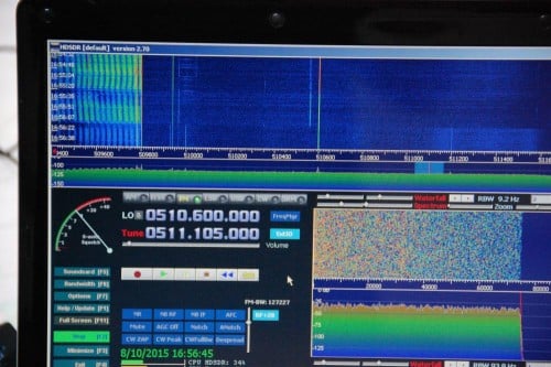
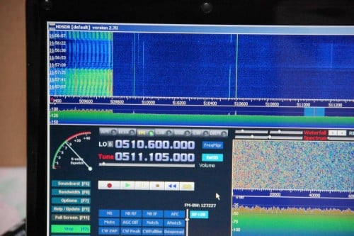
Reading up on Monopoles and their need for a ground plane, the magnetic base of the 14 cm long antenna was placed on a metal cooking pot. The signal was a lot stronger. (The middle part of the waterfall plot above.) Clearly a wooden table is not much of a ground plane.
Next a Corner Reflector was made from tinfoil and a cardboard box, much to the dismay of the resident Feline Overlord that had seized it. 🙂 A triangular piece was added for rigidity and as a ground plane. The Monopole antenna was placed on the ground plane triangle in the middle of the 90° corner and at the correct distance from the fold in the reflector. i.e. the Focal Axis, but the gain was less than the theoretical 10dB so this setup was unsuccessful. (Upper part of waterfall plot above.)
The breakthrough came when I wanted to study the effect of a larger ground plane. For this I put the corner reflector sideways and put the monopole on the outer edge to reduce possible reflections from the standing panel. There was only a slight effect compared to the cooking pot, so I decided to progressively move the monopole towards the back panel in order to see if the additional reflection would get some more gain. When I reached about 10 cm distance from the panel, the waterfall plot exploded with a very powerful signal! See the picture below for the transition from wooden table to the sideways configuration. (On top of the waterfall plot there is some residual from the ground plane cooking pot test.)

The setup looks like this:

For a few days I was baffled as to why the corner reflector behaved this way. It had already dawned on me that the diagonal distance from the fold till the antenna tip was 14 cm in this configuration, so 1/4 WL. It was only after I visualized how a monopole works, that I understood: a 1/4 WL monopole is physically a quarter wavelength open ended resonator. i.e. at the base/feed point the electric current is maximum and the voltage minimum. At the tip it is reversed, with maximum voltage and zero current. See this page for details: http://www.radio-electronics.com/info/antennas/vertical-antennas/quarter-wavelength.php
Alternatively, the polar plot of a Corner Reflector Antenna also shows that the signal is weakest/zero in the direction of the panels, where the monopole base is located, while the maximum signal is along the center line between the 2 panels, which is where the tip of the monopole is located. Hence the signal *difference* over the monopole is thus maximized and this way it works best. As stated in the beginning, if an antenna expert can write up a better explanation, please contact the maintainer of the RTL-SDR Blog.
In retrospect, the original setup I tested could not work optimal since the entire monopole is irradiated equally if it is aimed along the Focal Axis. Moreover it was suspected that the mirror image antenna that makes a monopole work, was distorted because of the electrical contact between the triangular ground plane and the reflector panels. A test with an isolated triangular ground plane was planned but has now been permanently shelved.
For those who want to re-create the experiment, these are the reflector dimensions:
- 2 panels of 42*25cm, joined along the longest side.
- 36*25*25cm triangle at the bottom. This should give a 90° angle between the 2 largest panels.
- The tinfoil can be wiped smooth and attached with some glue.
So to summarize;
- Make sure you have a good ground plane!
- A Corner Reflector Antenna can be constructed at frugal cost with a cardboard box and tinfoil. Larger reflectors are better, especially in the plane perpendicular to the Monopole, so it is better to have wide reflectors in stead of high reflectors.
- Make sure the base of the stock monopole antenna is located in an area with low signal strength and the tip is located in an area of maximum signal, therefore maximizing the *difference* between base and tip of the Monopole. Usually this means perpendicular to the Focal Axis of the reflector panels.
- Distances and Monopole lengths can easily be adjusted for various frequency ranges, making this a very versatile modification or enhancement to the stock antenna.
Speculation: Since there is a focal Axis rather than a Point (i.e. like a Parabolic Dish), the sideways configuration might be more suitable for tracking a moving satellite across the horizon, ideally at 45° azimuth.