We are giving away 20 of our new units with the metal case!
Competition has now ended! Thanks to all who entered! Winners to be announced by Monday.
The RTL-SDR and SDR community spans multiple disciplines and there are many wildly different projects being worked on by SDR enthusiasts as regular readers of our blog may already know. We want to thank all our readers with a competition and at the same time get everyone to share what projects you are all working on.
There are four chances to enter the contest and you may enter in all four competitions. On each method we will give away 5 RTL-SDR blog dongle + antenna units. Competition ends in one week on the 22nd of January at 23:59 hrs (midnight) PST time. Winners will be notified in the following 1-2 days and we will do a post about it too.
Competition Entry 1) Like us on Facebookand make a comment on the the contest post mentioning what SDR related projects you are currently working on, or plan to work on in the future.
Competition Entry 2) Follow us on Twitter and tweet at us @rtlsdrblog mentioning the SDR related projects you are currently working on, or plan to work on in the future.
Competition Entry 3) Make a comment on this very blog post mentioning what SDR related projects you are currently working on, or plan to work on in the future. (Please include a contact email address in the email field – it will only be visible to us and we won’t use it for anything else, promise!)
Competition Entry 4) Sign up to our email mailing list here or on the right hand navigation menu. (we send out a once weekly digest of the weeks posts).
We want to hear about any and all projects, no matter how simple you might think they are! At the end of the competition we will randomly select five winners from each competition entry method and contact them. Please remember to check your Facebook/Twitter/email accounts if your name comes up when the winners are announced.
Rules: Only one entry per person per method! E.g. you can enter once on Facebook, once on Twitter, once by commenting here, and once by signing up to our mailing list. No duplicate accounts are allowed. You must be legally be allowed to receive and own an RTL-SDR dongle to enter.
Currently we at RTL-SDR.com are selling upgraded RTL-SDR dongles on our store. We’ve worked hard to reduce the most common issues that the cheapest generic dongles have, whilst trying to not significantly increase the retail price so that these devices stay ubiquitous. In each batch that we’ve produced so far we’ve tried to make some improvements over the last. Previously we’ve added a TCXO, SMA connector, and bias tee and now in the latest batch we’ve added a metal case and passive cooling.
The new units have been in stock at our Chinese warehouse for almost a month now, and they are now back in stock at Amazon USA as well (shipping soon). They are priced the same as before: $24.95 USD for the unit with antennas and $19.95 USD for the dongle only. If you order from the Chinese warehouse all units come with free registered air mail shipping (1-4 week delivery), and free shipping is available on Amazon for USA customers (<1 week delivery) if you are a Prime member or spend over $35.
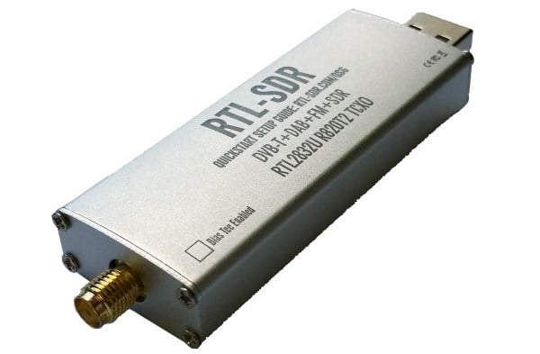
Aluminium case. We’ve upgraded from a plastic case and now all units come with an aluminium case standard. The aluminium is 1mm thick and is treated with an anti-anodizing coating to improve conductivity. However, some natural anodization still occurs. The dimensions are similar to the plastic case at 69 mm x 27 mm x 13 mm.
The new RTL-SDR dongle design with aluminium case.
Ground tracks on the PCB. The PCB size has been increased slightly to accommodate side ground tracks. These ground tracks should make contact with the aluminium and provide ground conductivity to the case.
New RTL-SDR PCB with side ground tracks.
Passive cooling. As the case is now metal we can apply a thermal interface material between the PCB bottom and case wall. The interface material we’ve chosen is a 3mm thermal pad. This is a soft silicon pad with high thermal conductivity. This appears to provide adequate cooling to ensure the dongles run properly at above 1.5 GHz.
Thermal pad on the bottom of the PCB for improved heat dissipation.
The metal case and side ground tracks should reduce the amount of interference received by the dongle through sources other than the antenna. The passive cooling should also be enough to ensure that the dongles run properly at above 1.5 GHz, though we still would recommend running them in a cool shady place, rather than out in the direct sun if monitoring L-band signals. If you find that the conductivity between the PCB and case is not good enough, then you can try thickening the side ground tracks on the PCB with a layer of solder – we will be trying to increase the thickness by default in subsequent batches.
Soon we will also have the metal cases for sale by themselves for those who want to upgrade from a previous batch (EDIT: Now on sale!). Though please note that although the older SMA PCBs fit in this case, the previous batches PCB’s are a little smaller than what this case takes so it may fit a little loosely. The old PCB’s also don’t have the side ground tracks for improved conductivity, but even with no ground conductivity it is still possible for the case to work as a Faraday cage. These cases will be available on the store page in a few days at a very low cost and they will only be available only from the Chinese warehouse.
Once again we hope people will enjoy these changes, and feel free to let us know what you think and what you might like to see in the future.
The SDRplay team have recently released a major update to their API and drivers. The new version is 1.8.0 and they write that it should remove the DC offset, reduce in band images from strong signals, and lower the noise floor. The SDRplay is a software defined receiver that costs $149 USD. They write:
We are pleased to announce release 1.8.0 of the API for the RSP. This is a major upgrade to the API with new features and an improved gain map which should result in improved performance over a key portion of the gain control range. Currently this API is available for Windows only, but versions for Linux and Mac OS and Android will follow shortly.
The API now incorporates automatic post tuner DC offset correction and I/Q compensation. This will almost completely eliminate the DC centre spike that was previously present in zero IF mode and also correct for amplitude and phase errors in the I/Q signal paths that can lead to in-band images when strong signals are present.
There is a new gain map for the RSP which should help improve the receiver noise floor for gain reduction settings in the range of 59-78 dB. To achieve this, the IF gain control range has been increased from 59 to 78 dB. In addition, the user can now turn the LNA on or off at any point within the IF gain control range. This means that the LNA can remain on for gain reduction settings of up to 78 dB, whereas previously the maximum gain reduction that could be attained whilst the LNA was on was only 59 dB. Being able to leave the LNA on will result in improvements in the receiver noise performance for gain reductions in the range of 59 to 78 dB. The upper 19 dB of the IF gain control range have now been disabled. In practice this part of the gain control range was useless as trying to operate within this region always lead to receiver overload even when signals were very weak.
To fully exploit the features of this new API release, we have also issued release 3.5 of the ExtIO plugin. This plugin will work with HDSDR, SDR sharp (releases 1361 or earlier) and Studio 1. Automatic I/Q compensation and DC offset correction will work with later versions of SDR sharp, but we will need to update the native plugin for users of these later versions to be access the new gain map.
Similarly, users of SDR Console will gain the benefit of automatic DC offset compensation and I/Q correction, but will not yet be able to access the new gain map. We hope that a version of SDR console that unlocks this feature will become available in the near future.
Until a new release of SDR-Console is available, you can copy the API into the SDR-Console installation directory…
from C:\Program Files\MiricsSDR\API\x64\mir_sdr_api.dll to C:\Program Files\SDR-RADIO-PRO.com\mir_sdr_api.dll
The API installer has also contains an extra certificate to be more user friendly for Windows XP, Vista and Windows 7 users.
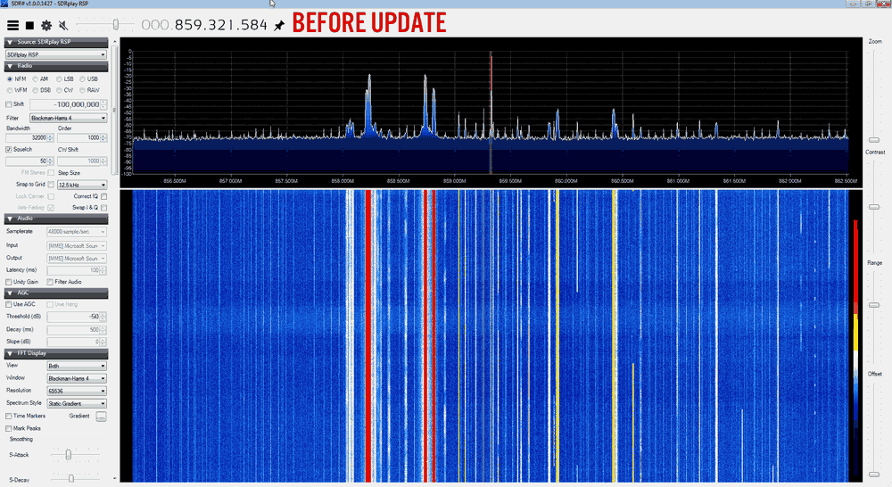
As they write that in band images from strong signals are reduced in this version we decided to do a quick before and after test using our own RSP receiver. We tuned into some TETRA signals that had exhibited images in the past on our RSP (you can see them as the yellow signals in the before image). In the new driver the images are completely gone.
We are giving away 20 of our new units with the metal case!
Competition has now ended! Thanks to all who entered! Winners to be announced by Monday.
The RTL-SDR and SDR community spans multiple disciplines and there are many wildly different projects being worked on by SDR enthusiasts as regular readers of our blog may already know. We want to thank all our readers with a competition and at the same time get everyone to share what projects you are all working on.
There are four chances to enter the contest and you may enter in all four competitions. On each method we will give away 5 RTL-SDR blog dongle + antenna units. Competition ends in one week on the 22nd of January at 23:59 hrs (midnight) PST time. Winners will be notified in the following 1-2 days and we will do a post about it too.
Competition Entry 1) Like us on Facebookand make a comment on the the contest post mentioning what SDR related projects you are currently working on, or plan to work on in the future.
Competition Entry 2) Follow us on Twitter and tweet at us @rtlsdrblog mentioning the SDR related projects you are currently working on, or plan to work on in the future.
Competition Entry 3) Make a comment on this very blog post mentioning what SDR related projects you are currently working on, or plan to work on in the future. (Please include a contact email address in the email field – it will only be visible to us and we won’t use it for anything else, promise!)
Competition Entry 4) Sign up to our email mailing list here or on the right hand navigation menu. (we send out a once weekly digest of the weeks posts).
We want to hear about any and all projects, no matter how simple you might think they are! At the end of the competition we will randomly select five winners from each competition entry method and contact them. Please remember to check your Facebook/Twitter/email accounts if your name comes up when the winners are announced.
Rules: Only one entry per person per method! E.g. you can enter once on Facebook, once on Twitter, once by commenting here, and once by signing up to our mailing list. No duplicate accounts are allowed. You must be legally be allowed to receive and own an RTL-SDR dongle to enter.
Currently we at RTL-SDR.com are selling upgraded RTL-SDR dongles on our store. We’ve worked hard to reduce the most common issues that the cheapest generic dongles have, whilst trying to not significantly increase the retail price so that these devices stay ubiquitous. In each batch that we’ve produced so far we’ve tried to make some improvements over the last. Previously we’ve added a TCXO, SMA connector, and bias tee and now in the latest batch we’ve added a metal case and passive cooling.
The new units have been in stock at our Chinese warehouse for almost a month now, and they are now back in stock at Amazon USA as well (shipping soon). They are priced the same as before: $24.95 USD for the unit with antennas and $19.95 USD for the dongle only. If you order from the Chinese warehouse all units come with free registered air mail shipping (1-4 week delivery), and free shipping is available on Amazon for USA customers (<1 week delivery) if you are a Prime member or spend over $35.
Aluminium case. We’ve upgraded from a plastic case and now all units come with an aluminium case standard. The aluminium is 1mm thick and is treated with an anti-anodizing coating to improve conductivity. However, some natural anodization still occurs. The dimensions are similar to the plastic case at 69 mm x 27 mm x 13 mm.
The new RTL-SDR dongle design with aluminium case.
Ground tracks on the PCB. The PCB size has been increased slightly to accommodate side ground tracks. These ground tracks should make contact with the aluminium and provide ground conductivity to the case.
New RTL-SDR PCB with side ground tracks.
Passive cooling. As the case is now metal we can apply a thermal interface material between the PCB bottom and case wall. The interface material we’ve chosen is a 3mm thermal pad. This is a soft silicon pad with high thermal conductivity. This appears to provide adequate cooling to ensure the dongles run properly at above 1.5 GHz.
Thermal pad on the bottom of the PCB for improved heat dissipation.
The metal case and side ground tracks should reduce the amount of interference received by the dongle through sources other than the antenna. The passive cooling should also be enough to ensure that the dongles run properly at above 1.5 GHz, though we still would recommend running them in a cool shady place, rather than out in the direct sun if monitoring L-band signals. If you find that the conductivity between the PCB and case is not good enough, then you can try thickening the side ground tracks on the PCB with a layer of solder – we will be trying to increase the thickness by default in subsequent batches.
Soon we will also have the metal cases for sale by themselves for those who want to upgrade from a previous batch (EDIT: Now on sale!). Though please note that although the older SMA PCBs fit in this case, the previous batches PCB’s are a little smaller than what this case takes so it may fit a little loosely. The old PCB’s also don’t have the side ground tracks for improved conductivity, but even with no ground conductivity it is still possible for the case to work as a Faraday cage. These cases will be available on the store page in a few days at a very low cost and they will only be available only from the Chinese warehouse.
Once again we hope people will enjoy these changes, and feel free to let us know what you think and what you might like to see in the future.
The SDRplay team have recently released a major update to their API and drivers. The new version is 1.8.0 and they write that it should remove the DC offset, reduce in band images from strong signals, and lower the noise floor. The SDRplay is a software defined receiver that costs $149 USD. They write:
We are pleased to announce release 1.8.0 of the API for the RSP. This is a major upgrade to the API with new features and an improved gain map which should result in improved performance over a key portion of the gain control range. Currently this API is available for Windows only, but versions for Linux and Mac OS and Android will follow shortly.
The API now incorporates automatic post tuner DC offset correction and I/Q compensation. This will almost completely eliminate the DC centre spike that was previously present in zero IF mode and also correct for amplitude and phase errors in the I/Q signal paths that can lead to in-band images when strong signals are present.
There is a new gain map for the RSP which should help improve the receiver noise floor for gain reduction settings in the range of 59-78 dB. To achieve this, the IF gain control range has been increased from 59 to 78 dB. In addition, the user can now turn the LNA on or off at any point within the IF gain control range. This means that the LNA can remain on for gain reduction settings of up to 78 dB, whereas previously the maximum gain reduction that could be attained whilst the LNA was on was only 59 dB. Being able to leave the LNA on will result in improvements in the receiver noise performance for gain reductions in the range of 59 to 78 dB. The upper 19 dB of the IF gain control range have now been disabled. In practice this part of the gain control range was useless as trying to operate within this region always lead to receiver overload even when signals were very weak.
To fully exploit the features of this new API release, we have also issued release 3.5 of the ExtIO plugin. This plugin will work with HDSDR, SDR sharp (releases 1361 or earlier) and Studio 1. Automatic I/Q compensation and DC offset correction will work with later versions of SDR sharp, but we will need to update the native plugin for users of these later versions to be access the new gain map.
Similarly, users of SDR Console will gain the benefit of automatic DC offset compensation and I/Q correction, but will not yet be able to access the new gain map. We hope that a version of SDR console that unlocks this feature will become available in the near future.
Until a new release of SDR-Console is available, you can copy the API into the SDR-Console installation directory…
from C:\Program Files\MiricsSDR\API\x64\mir_sdr_api.dll to C:\Program Files\SDR-RADIO-PRO.com\mir_sdr_api.dll
The API installer has also contains an extra certificate to be more user friendly for Windows XP, Vista and Windows 7 users.
As they write that in band images from strong signals are reduced in this version we decided to do a quick before and after test using our own RSP receiver. We tuned into some TETRA signals that had exhibited images in the past on our RSP (you can see them as the yellow signals in the before image). In the new driver the images are completely gone.
SvxLink is an EchoLink and general purpose voice services system for controlling ham radio repeaters. A repeater is a radio tower that receives a weak transmission from a handheld or remote radio and then repeats the same message with greater power over a wide area. With repeaters radio communications can cover a much further distance.
Ham radio enthusiasts often set up repeaters for their own frequencies, so that they can be heard over a wider range. To control the repeater software like SvxLink is required. In the latest software update of SvxLink they added RTL-SDR support. They write:
The biggest news in this release is the support for RTL2832U based DVB-T USB dongles. This make it possible to use such USB dongles as cheap SDR (Software Defined Radio) receivers. This will open up the world of cheap receiver hardware to all SvxLink users. It will for example be very cheap to set up an extra receiver with local coverage for a SvxLink based repeater, as long as there is a network connection to the repeater. The modulation forms supported are: FM, FM narrow, AM, AM narrow, USB, LSB, CW, CW wide and wideband FM (broadcast). Running multiple receivers on the same dongle is supported as well as using multiple dongles.
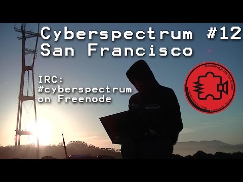
Cyberspectrum is a monthly software defined radio meetup that is held in San Francisco. During this meetup presenters show and discuss their SDR related work. The 12th Cyberspectrum meetup is occurring right now and this time there will be presentations from amateur radio astronomer Marcus Leech from Canada and wireless security researcher Tobias Zillner from Austria.
There is a live stream on YouTube shown below, and after it finishes it will also be available for viewing:
Edit: Stream is over. Marcus Leech gave a nice talk that gave an overview or amateur radio astronomy and explained some of his set up where he uses RTL-SDR dongles as the receiver.
Cyberspectrum: Bay Area Software Defined Radio #12 (Dec 2015)
The overview of today’s presentations are as follows:
• Marcus Leech from SBRAC: “An integrated proof-of-concept ‘all-digital’ feed for 21cm radio astronomy”
We show ongoing work in designing and building a proof-of-concept ‘all digital’ feed for 21cm radio astronomy experiments. While many professional radio astronomy observatories are using “digitize at the feed” techniques, amateur experiments (and successes) in this are very close to non-existent.
Digitizing at the feed carries many advantages, including overall system gain stability, and the ability to carry signals over cheap ethernet-over-fiber links.
We’ll show an example feed arrangement that uses a differential radiometry approach, and does much of the initial processing right at the feed, including radiometry and spectral calculations, sending summary data to an ordinary PC host over ethernet.
Challenges and pitfalls will be discussed.
• Tobias Zillner from Cognosec: “ZigBee Smart Homes – A Hacker’s Open House”
ZigBee is one of the most widespread communication standards used in the Internet of Things and especially in the area of smart homes. If you have for example a smart light bulb at home, the chance is very high that you are actually using ZigBee by yourself. Popular lighting applications such as Philips Hue or Osram Lightify and also popular smart home systems such as SmartThings or Googles OnHub are based on ZigBee. New IoT devices have often very limited processing and energy resources. Therefore they are not capable of implementing well-known communication standards like Wifi. ZigBee is an open, public available alternative that enables wireless communication for such limited devices.
ZigBee provides also security services for key establishment, key transport, frame protection and device management that are based on established cryptographic algorithms. So a ZigBee home automation network with applied security is secure and the smart home communication is protected?
No, definitely not. Due to “requirements” on interoperability and compatibility as well as the application of ancient security concepts it is possible to compromise ZigBee networks and take over control of all included devices. For example it is easily possible for an external to get control over every smart light bulb that supports the ZigBee Light Link profile. Also the initial key transport is done in an unsecured way. It is even required by the standard to support this weak key transport. On top of that another vulnerability allows third parties to request secret key material without any authentication and therefore takeover the whole network as well as all connected ZigBee devices. Together with shortfalls and limitations in the security caused by the manufacturers itself the risk to this last tier communication standard can be considered as highly critical.
This talk will provide an overview about the actual applied security measures in ZigBee, highlight the included weaknesses and show also practical exploitations of actual product vulnerabilities. Therefore new features in the ZigBee security testing tool SecBee will be demonstrated and made public available.
The Free and Open Source Developers Meeting (FOSDEM) is looking for SDR presentations to give at this years conference in Brussels, Belgium which will be held on January the 80th & 31st of January.
Software Radio has become an important tool to allow anyone access the EM spectrum. Using free software radio libraries and applications and cheap hardware, anyone can now start hacking on wireless communications, remote sensing, radar or other applications. At FOSDEM, we hope to network all these projects and improve collaboration, bring new ideas forward and get more people involved.
The track’s web site resides at: http://gnuradio.org/redmine/projects/gnuradio/wiki/FOSDEM
Here, we will publish updates and announcements. The final schedule will be available through Pentabarf and the official FOSDEM website.
To suggest a talk, go to https://penta.fosdem.org/submission/FOSDEM16 and follow the instructions (you need an account, but can use your account from last year if you have one). You need to create an ‘Event’; make sure it’s in the Software Defined Radio track! Lengths aren’t fixed, but give a realistic estimate and please don’t exceed 30 minutes unless you have something special planned (in that case, contact one of us). Also, don’t forget to include time for Q&A. Typical slot lengths would be 30 Minutes including QA.
You aren’t limited to slide presentations, of course. Be creative. However, FOSDEM is an open source conference, therefore we ask you to stay clear of marketing presentations. Of course, we like nitty-gritty technical stuff.
We will reserve time for interactiveness, it won’t all be talks.
If you are qualified and interested in giving a talk the submission deadline is December 4th 2015.
The prototype watch does this by using the RTL-SDR to detect the electromagnetic (EM) noise emitted by particular objects and compare it against a stored database. They call this technology EM-Sense. In the paper the authors summarize:
Most everyday electrical and electromechanical objects emit small amounts of electromagnetic (EM) noise during regular operation. When a user makes physical contact with such an object, this EM signal propagates through the user, owing to the conductivity of the human body. By modifying a small, low-cost, software-defined radio, we can detect and classify these signals in real-time, enabling robust on-touch object detection. Unlike prior work, our approach requires no instrumentation of objects or the environment; our sensor is self-contained and can be worn unobtrusively on the body. We call our technique EM-Sense and built a proof-of concept smartwatch implementation. Our studies show that discrimination between dozens of objects is feasible, independent of wearer, time and local environment.
The frequencies required for EM detection are around 0 - 1 MHz which falls outside the range of the RTL-SDR's lowest frequency of 24 MHz. To get around this, they ran the RTL-SDR in direct sampling mode. The RTL-SDR is connected to the watch, but a Nexus 5 smartphone is used to handle the USB processing which streams the signal data over WiFi to a laptop that handles the signal processing and live classification. In the future they hope to use a more advanced SDR solution, but the RTL-SDR has given them the proof of concept needed at a very low cost.
An example use scenario of the watch that Disney suggests is as follows:
Home – At home, Julia wakes up and gets ready for another productive day at work. Her EM-Sense-capable smartwatch informs and augments her activities throughout the day. For instance, when Julia grabs her electric toothbrush, EMSense automatically starts a timer. When she steps on a scale, a scrollable history of her weight is displayed on her smartwatch automatically. Down in the kitchen, EM-Sense detects patterns of appliance touches, such as the refrigerator and the stove. From this and the time of day, EM-Sense infers that Julia is cooking breakfast and fetches the morning news, which can be played from her smartwatch.
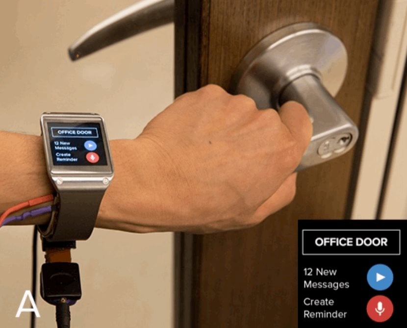
Fixed Structures – When Julia arrives at the office, EMSense detects when she grasps the handle of her office door. She is then notified about imminent calendar events and waiting messages: "You have 12 messages and a meeting in 8 minutes". Julia then leaves a reminder – tagged to the door handle – to be played at the end of the day: “Don’t forget to pick up milk on the way home.”
Workshop – In the workshop, EM-Sense assists Julia in her fabrication project. First, Julia checks the remaining time of a 3D print by touching anywhere on the print bed – “five minutes left” – perfect timing to finish a complementary wood base. Next, Julia uses a Dremel to cut a piece of wood. EM Sense detects the tool and displays its rotatory speed on the smartwatch screen. If it knows the task, it can even recommend the ideal speed. Similarly, as Julia uses other tools in the workshop, a tutorial displayed on the smartwatch automatically advances. Finally, the 3D print is done and the finished pieces are fitted together.
Office – Back at her desk, Julia continues work on her laptop. By simply touching the trackpad, EM-Sense automatically authenticates Julia without needing a password. Later in the day, Julia meets with a colleague to work on a collaborative task. They use a large multitouch screen to brainstorm ideas. Their EM-Sense-capable smartwatches make it possible to know when each user makes contact with the screen. This information is then transmitted to the large touchscreen, allowing it to differentiate their touch inputs. With this, both Julia and her colleague can use distinct tools (e.g., pens with different colors); their smartwatches provide personal color selection, tools, and settings.
Transportation – At the end of the day, Julia closes her office door and the reminder she left earlier is played back: “Don’t forget to pick up milk on the way home.” In the parking lot, Julia starts her motorcycle. EM-Sense detects her mode of transportation automatically (e.g., bus, car, bicycle) and provides her with a route overview: “You are 10 minutes from home, with light traffic”.
The EM-Sense watch detecting a door. The RTL-SDR dongle is the small square box under the watch.
EM-Sense: Touch Recognition of Uninstrumented Electrical and Electromechanical Objects
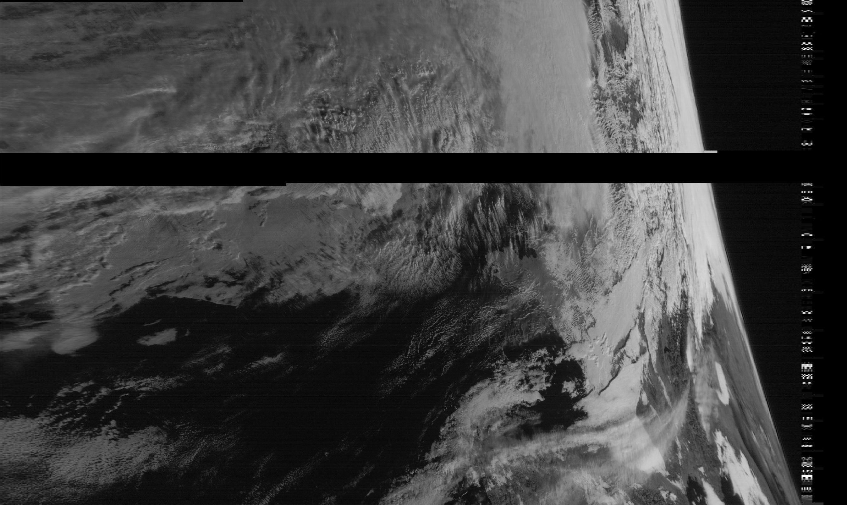
RTL-SDR.com reader Happysat recently wrote in with some news. A few days ago a weather satellite image decoding enthusiast from Argentina was waiting for a pass of the Russian Meteor M-N2 satellite when he discovered a strong LRPT signal at 137.1 MHz, even though the Meteor M-N2 satellite was not in sight yet. It turns out that the signal was coming from the old Meteor M-N1 satellite which was supposed to have been shut down in September 2014 due to several problems it had. The received signal is strong enough to produce a good black and white weather image, but because the satellite is not longer physically stable, sometimes the Earth’s curve can be seen in the images.
Recent images received from the resurrected Meteor M-N1 weather satellite.Recent images received from the resurrected Meteor M-N1 weather satellite. The stabilization system has failed so the earth’s curve can be seen.
The exact reason as to why it is transmitting again is unknown, but it is speculated that it is due to a breakdown of the chemicals in the batteries. Last year we posted about how sometimes satellites which have been decommissioned and shut down can spontaneously begin transmitting again when their batteries undergo a chemical change due to thousands of failed recharge cycles. The chemical change allows the batteries to conduct electricity from the solar panels directly to the electronics, which on Meteor M-N1 could be reactivating the transmitters and imaging sensors. If this is what happened then the satellite will only be able to transmit during the day.
The Meteor M-N2 satellite is the currently official active satellite. It transmits weather satellite images with the LRPT protocol which can be received and decoded with an RTL-SDR dongle. We have a previous post on this showing an offline LRPT decoding tutorial and more recently a tutorial showing how to decode LRPT in real time. The same processes can now be adapted to the resurrected Meteor M-N1 satellite by choosing the 80K symbol rate option in the LRPT decoder.
Happysat who submitted this news originally writes:
A few days ago some guy in Argentina was waiting for the pass of Meteor M-N2 and on SDRSharp waterfall he did see LRPT Digital signals on 137.100MHz, but Meteor M-N2 was not in sight yet…
This relatively strong signal was coming from the defunct Meteor M-N1 satellite left out of control in September 2014 last year and was shutdown, although LRPT Transmissions in the past where very limited and sporadic.
Meteor M-N1 did suffer from many problems at this was the first Russian digital weather satellite in the M-series onboard many hardware in experimental stages.
After this report I tried also to capture some signals from Meteor M-N1 (some other amateurs already got small portions of images) but the satellite only transmits in direct sunlight, batteries are not charging any more.
Indicating maybe like the other older ‘deadsat’ some chemical reaction did occur inside the batteries so the power goes from the solar panels directly to the transmission parts. It did happen before, mostly on older satellite’s only a unmodulated carrier is present when the sunlight conditions are optimal.
Surprisingly after I did record and process the 80K symbol rate QPSK signal from Meteor M-N1 with Vasili’s excellent QPSK Plugin a very nice image was generated!
Not only the sunlight provides power to the transmission part but also there is enough power to activate the imaging system which is quite amazing!
Visible channels 1-2-3 are fully working but the image is only Black and White Calibaration of the sensor are not okay so no color images can be created.
Nevertheless its a very nice addition for current LRPT weather amateurs and a big surprise its even working better when nobody controls it 😉
Because the stabilisation system failed there is no proper correction to orientate the camera and on some passes one can see the earths curve!
There are some conflicting reports about the status of Meteor M-N1 found on the internet:
Status Inactive Details on Status (as available)
MSU-MR was functional with limitations (calibration issues and higher noise level in the IR channels).
MTVZA-GY instrument was functional with limitations due to failures of on-board memory and atmospheric sounding channels.
Severjanin instrument non-operational.
DCS was functional with limitations due to interferences to signals from ground sources.
GGAK-M was operational with significant limitations.
LRPT was functional with limitations due to information compression errors.
Finally, the stabilisation system failed on 23 September 2014 and the instruments could longer be operated.
On October 1, 2014 Meteor-M No 1 was withdrawn from operational use and transferred to the study of the chief designer. The decision on further operation of the spacecraft will be taken upon completion of the research program.
Its not clear the problems did got solved, and I ‘think’ M-N1 started a second life on his own. Time will tell how long the satelitte will function.