Category: RTL-SDR

RTL-SDR Front End Filter Demonstration

Over on YouTube user kugellagers has uploaded a video demonstrating the effect of some front end filters he constructed in order to reduce the effects of intermodulation from strong local AM and FM broadcast radio stations.

To attenuate strong broadcast FM signals, he used a very cheap FM trap from MCM Electronics. An FM trap (aka FM bandstop filter) is designed to attenuate signals in the FM band only. However, as a single FM trap was not strong enough for him, he took two FM traps out of their original casing and connected them together in a larger box for increased attenuation.

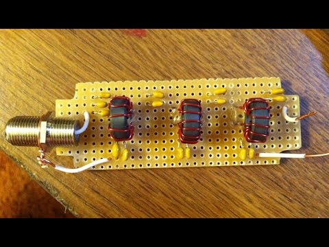
To attenuate strong broadcast AM signals he designed and created a home made 7th order LC elliptic high pass filter. With the filter in place he is able to receive a station at 2.5 MHz, but without it he shows that is unable to receive it clearly due to broadcast AM intermodulation.

RTL SDR Front End Filter Demonstration

Analyzing the Radio Spectrum in Hong Kong with an RTL-SDR

Over on his blog, Gough Liu has made a post showing an analysis of the Hong Kong radio spectrum that he made while he was on a trip. In his analysis Gough used a locally bought DMB-T TV dongle (not RTL-SDR) for receiving digital TV and DAB+, a Dengen DE1103 for receiving AM and FM Broadcast and an RTL-SDR dongle for all other signals.

In his post Gough first talks about how he received DTM-B digital TV broadcast (similar to DVB-T and ATSC), and he does a full analysis of this service in another post. Next Gough talks about the Hong Kong digital radio DAB+ service and his finding where he saw that there was significant multipath selective fading in the DAB+ signal. He also found out that the HK DAB+ service broadcasts still images along with the audio.

Next Gough received the broadcast FM band and found that it was extremely crowded, providing poor distorted audio quality. He also attempted shortwave listening, but massive amounts of local interference prevented him from doing so.

Finally Gough took advantage of his harbour view hotel room to use his RTL-SDR to receive marine AIS transmissions. He used AISMon and OpenCPN to plot the boat positions on a map.

DAB+ Multipath Selective Fading in Hong Kong

RTL-SDR Live Discussion Net at 8pm EDT Tonight

Over on Reddit amateur radio hobbyist K2RWF has posted about a live discussion and QA session that he and some others will be having on a amateur radio net about RTL-SDR dongles. The discussion begins at 8PM EDT (about 2 hours from time this is posted) and will run for about an hour. For non-hams the discussion can be streamed live from http://rfissel.no-ip.biz:8080/stream.m3u. On the post K2RWF writes:

We had a pretty successful net last week regarding the RTLSDR sticks that are now widely available. We’ve decided to make the net a weekly occurrence for the time being, every Wednesday at 8 pm.

Tonight, we will be covering basic setup and configuration of the sticks from a software and hardware perspective, answering any questions you may have about getting up and running.

The net originates on W2LI, and tonight, we will be linked to the W2NJR repeater network, covering NJ and parts of NYC. This includes Echolink (21005) and IRLP (4935) capabilities for those wishing to participate from outside the area. The net beings at 8 pm EDT, and is expected to run for about one hour.

All are welcome, from newbies through advanced users. For non hams wishing to participate, you may stream the net using the link provided below. We will also be monitoring this thread to yield and answer questions from the r/rtlsdr community.

http://rfissel.no-ip.biz:8080/stream.m3u

Update: Recording of the net can be downloaded here (mp3)

Listening to an NFC Polling Signal from a Nexus 7 with an RTL-SDR

Over on YouTube user 2e26tenW has uploaded a video showing reception of the second harmonic of an NFC polling signal with his RTL-SDR. NFC stands for “Near Field Communication” and is a technology that enables smartphones and other devices to communicate with one another and some smart cards simply by bringing the two devices together.

In his experiment he uses a Nexus 7 tablet to poll an NFC enabled transportation card. As the RTL-SDR cannot receive the NFC frequency of 13.56 MHz directly without an upconverter or hardware or software direct sampling modified dongle, 2e26tenW instead tunes to the second harmonic at 27.12 MHz which allows him to receive the signal.

Nexus 7 NFC polling signal (2nd harmonic)

Low Pass Filter for RTL-SDR Direct Sampling Mode

Over on his blog (in Japanese) Nobu has been working on prototyping a 14 MHz low pass filter (LPF) product for direct sampling modified RTL-SDR dongles (in Japanese, use Google Translate). Direct sampling mode is a hardware modification that allows the tuner chip in RTL-SDR dongles to be bypassed, allowing reception of signals between 0 – 14 MHz. However, after performing this mod there is no filtering and images from higher frequencies such as broadcast FM can be problematic. To fix these problems a low pass filter is required.

Another product Nobu is working on is an isolation transformer (aka Galvanic Isolator) which can be used together with an upconverter to help reduce noise generated from common ground sources such as the PC. The isolation transformer is inserted between an upconverter and antenna.

Low Pass Filter (Top), Isolation Transformer (Bottom)

In the image below Nobu shows the effect of inserting the LPF . An interfering FM broadcast band signal is removed after inserting the LPF.

Effect of inserting the Low Pass Filter

The image below shows the effect of the isolation transformer showing a clear decrease in noise floor and increase in signal strength.

Effect of an Isolation Transformer when used with an Upconverter

Video Showing Decoding of DGPS Beacons with SDR# and MultiPSK

Following on from our last post where dewdude showed how to decode DGPS signalsFrank K2NCC has uploaded a video on YouTube showing DGPS decoding in action. In his video Frank uses an Airspy plus ham-it-up upconverter, a Sirio discone antenna and for software he uses SDR# with audio piped into MultiPSK for decoding.

In the video you can clearly see the decoded DGPS messages showing the pseudorange corrections and station numbers. To decode DGPS with MultiPSK you will need to use the paid version which costs approximately $50 USD, however in the free version the DGPS will run for 5 minutes each time MultiPSK is opened before expiring.

Below is an example of a decoded message.

24/03/2015 02:06:09
Message type        : 9 (GPS partial correction set)
Station number      : 172 (Appleton WA USA 300.0 Khz TXID 871 100bps)
Z-count             : 4215 ( 42 mn 9.0 s )
Sequence count      : 2le factor=0.3)

Sat. ID|SF|UDRE|Pseudorange corr.  |Range rate corr.|IOD|CRC
25     |0 |1-4m|      -7.68 m      |   0.000 m/s    |62 |OK
31     |0 |1-4m|       1.54 m      |   0.000 m/s    |27 |OK
32     |0 |1-4m|       0.70 m      |   0.000 m/s    |99 |Error

Decoding Differential GPS Beacons with an RTL-SDR, Speclab and SDR#

Over on his blog “RTL-SDR DX” dewdude has been exploring the reception and decoding of Differential GPS (DGPS) signals. DGPS signals are transmitted by government authorities in the long wave band at around 300 kHz. These beacons are used to dramatically improve the accuracy of GPS (Global Positioning System) devices from their default accuracy of about 15 m down to about 10 cm. Unlike GPS signals which originate from satellites, the DGPS signal is terrestrial based and is broadcast from multiple known fixed positions. The signal itself contains information about the difference between the DGPS stations received GPS position and it’s known exact position. These differences can be used to correct other GPS receivers that receive DGPS signal.

By using his RTL-SDR (with upconverter or HF modification) dewdude was able to receive the DGPS beacon in SDR#. Then by piping the output audio into SpectrumLab’s DGPS decoder he was able to decode the data contained within the DGPS signal. His post contains a tutorial showing how to set up SpectrumLab to decode DGPS. If you’re interested in hearing what a DGPS signal sounds like, dewdude has uploaded a sound sample at the bottom of another post of his.

Decoding Differential GPS (DGPS) signals in SpectrumLab

A Faster Method for Decoding Meteor M2 Weather Satellite Images

Over on YouTube user max30max31 aka IZ5RZR has uploaded a video that shows a faster method for decoding Meteor M2 weather satellite images on a Windows system.  The Meteor-M N2 is a Russian weather satellite that transmits images using the LRPT protocol at around 137.1 MHz with can be received with an RTL-SDR. Compared to NOAA satellite APT images, LRPT images are much higher in resolution.

Normally, decoding Meteor M2 LRPT images requires a post processing step which involves the use of Audacity, an audio editing suite to reduce the recorded IQ files sample rate. However, with the recently released decimation SDR# drivers the Audacity step can be avoided by using a an appropriate decimation factor (8 at 1.024 MSPS) when recording the LRPT signals IQ data.

Post processing still involves the use of the Lrptrx.exe software, Oleg’s LRPToffLineDecoder to produce the image and SmoothMeteor to remove distortion from the image..

IZ5RZR - Fast decode Meteor M2 satellite - 2015