Thanks to Manuel (aka Tysonpower) for writing in and sharing his 3D printed ‘Universal Outernet Case’. Outernet is a satellite file casting service that uses an RTL-SDR based solution for reception. With an Outernet set up you can receive things like daily news, weather updates, books, Wikipedia pages and more all for free. About 20 MB of data can be transmitted in one day.
The DIY Outernet kit consists of an RTL-SDR ‘SDRx’ board, patch antenna and C.H.I.P single board computer. The patch antenna needs to point roughly in the direction of the Inmarsat/Alphsat satellite in your area. This can be a problem because the Outernet patch antenna doesn’t come with a stand or mounting solution.
Manuel solved this problem with his 3D printed Outernet enclosure. The enclosure houses the patch antenna, SDRx and C.H.I.P, and also doubles as a stand for pointing the patch antenna. Inside he’s also fitted a small 30mm fan to keep everything cool while inside the enclosure as the C.H.I.P is known to have overheating problems.
The 3D printed Outernet enclosure.
Over on YouTube Manuel has uploaded a video explaining how the enclosure is made with 3D printing, demonstrates the assembly steps and finally shows the final product. The video is narrated in German, but it has English subtitles available. The design files required for 3D printing the case are also available on thingiverse.
[EN subs] Outernet Case aus dem 3D Drucker (Universal elv. Winkel) - für DIY Kit
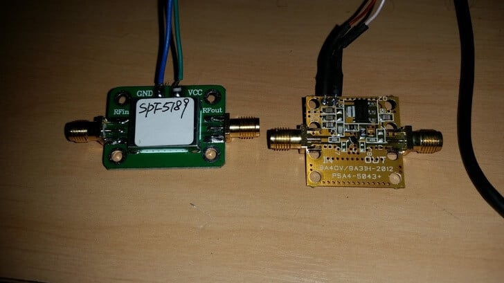
Over on his blog Lucas Teske has been comparing the LNA4ALL and an SPF5189 LNA from eBay on HRIT/LRIT reception from GOES satellites. SPF5189 LNA’s can be found on eBay for less than $8 USD, with free shipping from China, whereas the LNA4ALL costs 27 Euros shipped from Croatia. GOES is a geosynchronous orbit weather satellite which requires a satellite dish or other high gain antenna to receive. It downlinks at about 1.7 GHz, which means that a high quality LNA with low noise figure and good PCB design is needed for reception.
In his post Lucas mentions how he saw a review on eBay stating that the SPF5189 did not work at L-band. However, he found that odd as all of his SPF5189 LNA’s seemed to work just fine with L-band reception. So he did a benchmark comparing the SPF5189 to the PSA5043+ based LNA4ALL which is known to work well on L-band.
From his comparisons he found that the SPF5189 does indeed work well on L-band, and is comparable to the LNA4ALL. He concludes that the reviewer must have received a bad unit, or didn’t know what he was doing.
Lucas also makes an important note regarding the PCB design of these LNA’s. Even though the SPF5189 and PSA5043 chips have similar specs, with LNA’s the design of the PCB is crucial, as a poor design can significantly degrade performance. With the LNA4ALL you can be sure that the design is good, although the SPF5189 LNA’s currently on eBay look to be designed okay as well. Though with some eBay sellers there is no guarantee that you will receive a good board. We note that we have seen some really poor designs for PSA5043 LNA’s out there as well.
This software decoder appears to be an excellent choice for those people who want to perform their reception and decoding of Meteor M satellites all in Linux. Previously as explained in this previous post, you were able to receive the QPSK data in Linux with an RTL-SDR and a GNU Radio program, but then you’d still need to boot into Windows or run Wine to run LRPTofflinedecoder in order to generate the image. Now it appears that the image generation can be performed natively in Linux too with meteor_decoder. This help with creating portable automated Raspberry Pi based Meteor M decoder servers.
Meteor M is a class of Russian weather satellites that transmit live weather images of the earth as they pass over your location. They are somewhat similar to the NOAA satellites, although the Meteor satellites transmit higher quality images via a digital LRPT signal, rather than the analog APT signals used by NOAA. With an RTL-SDR, an appropriate antenna and decoding software they can easily be received.
An Example LRPT Image Received with an RTL-SDR from the Meteor M-N2 Satellite.
RF bypass for tuning from 24 – 1600 MHz – use as a regular RTL-SDR!
USB ports
GPIO forest
UARTs, I2C, SPI headers (unpopulated) for driving external hardware
Two microSD card holders – for boot and storage!
1 GHz CPU
256 MB RAM Now 512 MB RAM
USB wifi dongle (not shown) – STA+ AP mode capable!
Lots of LEDs! and Switches!
microUSB OTG
microUSB power port
Audio In/Out
Speaker with 1.4 W integrated audio amplifier
Fully mainline (4.10) Kernel and (2017.01) Uboot support! *** JST battery is being removed
On the Roadmap:
armbian/debian support
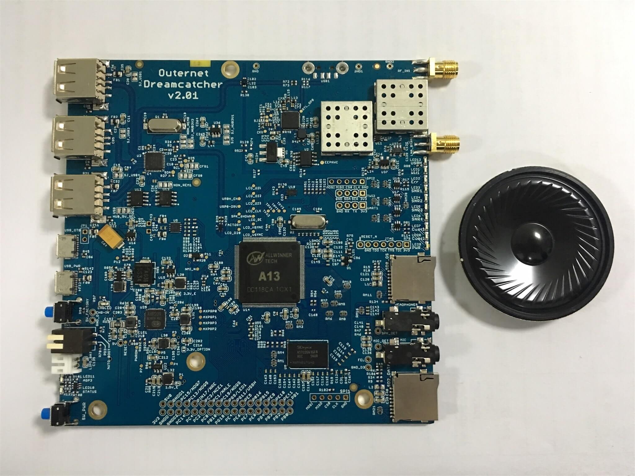
This is a fully-integrated SDR receiver – RF frontend, SDR, Compute, Wifi – Everything!
Outernet is an L-band satellite service that aims to be a download only “library in the sky”. Currently they are broadcasting from Inmarsat and Alphasat geostationary satellites which can be received from almost anywhere in the world. We have a tutorial on receiving and decoding their signal here. Every day almost 20 MB of data is sent down, and this includes data like news, weather forecasts, APRS, wikipedia articles, books and more. In the future you will be able to pay to upload private files or messages. This could be useful for sending messages to people isolated from cell phone reception, or for operating remote hardware.
Previously Outernet sold a DIY version of their receiver which included an RTL-SDR V3 or E4000 dongle, LNA+filter, a C.H.I.P embedded computer, and a patch antenna. Recently they have changed to their custom RTL-SDR hardware which is called the “SDRx”. The SDRx includes the RTL-SDR, LNA and filter on a single PCB. Over time it seems that they are moving in the direction of integration of all components onto a single PCB and this can be seen in the Dreamcatcher which now also includes the computing hardware. This is especially good news as the $9 C.H.I.P computing hardware has been almost impossible to acquire since its release.
The Dreamcatcher looks to be also not just useful for Outernet, but also for general projects that can be done on embedded hardware as there is a port which bypasses the L-Band filter.
Back in 2014 we posted about the XiOne. This was also to be an RTL-SDR and computing hardware built onto the same PCB. It would have been controlled via a WiFi connection and apps on a smart phone/tablet. Unfortunately the XiOne Indiegogo crowdfunding campaign never reached its target so the project faded away. The Dreamcatcher is somewhat similar in that both are RTL-SDRs with onboard computing hardware and WiFi connectivity.
The Dreamcatcher is not yet for sale, but it is currently under production. From the looks of the discussion on the forums, it looks like it will sell for $149 USD. Outernet have said that they are sending us a review sample, so keep an eye out for the review in the coming weeks.
The Outernet Dreamcatcher: RTL-SDR + LNA + Filter + Computing Hardware on a single PCB.
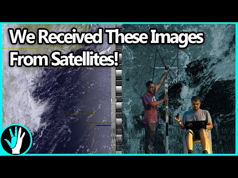
Over on the Thought Emporium YouTube channel the team have uploaded two videos that may be of interest to radio hobbyists. The first video shows a nice overview about receiving NOAA weather satellite images. They explain everything from scratch for complete novice, so the videos are great for almost anyone to watch and learn about radio and SDR concepts. The blurb of the first video reads:
Over the past 2 months, me and my friend Artem have been building antennas to receive signals from weather satellites as they pass overhead. This video chronicles our progress through this project and goes through some of the science involved in working with radio and receiving transmissions. We explore how dipoles work and how to build them, and how we built our final double cross antenna. We used an SDR (software defined radio) called a HackRF to do the work of interpreting the received signals and then decoded them with some special software. We pulled images from 4 satellites: NOAA 15, 18 and 19 as well as METEOR M2. The satellites broadcast immediately as they take the images and no images are stored, so we’re likely the only ones on earth with these images.
How to Pull Images from Satellites in Orbit (NOAA 15,18,19 and METEOR M2)
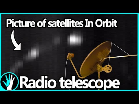
The second video is about building a radio telescope. Like the NOAA video, they explain all concepts in a simple and easy to understand way, so that anyone even without any radio knowledge can understand what the project is about. In the video they also show how they use a 3D printer to create a tracking mount which can point a satellite dish. They then use the dish to create a satellite heat map. The blurb reads:
Over the last 2 months me and my friend Artem (you met him in the last video) built our first radio telescope. It was built mostly out of off the shelf components, like a satellite dish and Ku band LNB, as well as some parts we 3d printed. When all was said and done we had a system that could not only take images of the sky in radio frequencies (in this case 10-12ghz), but could also be used to track satellites. With it, we were able to see the ring of satellites in geosynchronous orbit, over 35,000km away, This is only the first of what I suspect will be many more telescopes like this. Next time we’ll be building ones that are far larger and can see things like the hydrogen lines so we can image the milky way.
How to Build a Radio Telescope (See Satellites 35,000km Away!)
The Tekmanoid EGC STD-C decoder was recently updated and a new commercial paid version was released. The paid version now supports the decoding of LES STD-C messages. Previously the only other decoder that we knew of which was able to decode LES messages was the www.inmarsatdecoder.com software. The inmarsatdecoder.com software costs €100, and while the price for the Tekamanoid decoder is not advertised, it is less than €100, and a bit more affordable for the average person.
Tekmanoid STD-C Decoder Receiving LES Message.
The free versions of both decoders only decode the EGC broadcast messages which contain SafetyNET messages. These include messages like weather reports, shipping lane activity and hazards such as submarine cables and oil rig movements, pirate activity, refugee ship reports, missing ship reports, and military exercise warnings.
The paid version can decode the other non-broadcast private LES STD-C channels. LES STD-C channels typically contain email like messages sent to and from ships. Mostly it’s company messages about the ship route plans, cargo discussions, repair/fault discussions, ship performance information and weather reports etc. Sometimes small files are also downloaded. Each Inmarsat satellite contains about 7 LES channels each run by a different telecommunications company, so one may be of interest to you.
The paid version of the Tekmanoid decoder also has a nice feature for visualizing the SafetyNET EGC messages. Every now and then an alert containing coordinates and an area is sent out. Usually it is something like a distress alert from an EPIRB or the search area for a missing vessel. The decoder generates an HTML file that displays these areas on a map, alongside the text message.
STD-C EGC Distress Alert on map
The author of the Tekamnoid software allowed us to test his new paid version for free. We ran the software using signal from an Outernet patch antenna and LNA. An RTL-SDR V3 + SDR# was used as the receiver, and the audio was piped to the Tekmanoid decoder with VB-Cable. Decoding was almost flawless on both LES and EGC STD-C channels. In a previous recent update the Tekmanoid decoder was updated for improved decoding performance, and now in our opinion it is almost or just as good as the inmarsatdecoder.com software.
If you are interested in learning more about decoding Inmarsat STD-C we have a tutorial available here. LES channels for the Inmarsat satellite in operation over your geographic location can be found on UHF-Satcom’s website.
LES STD-C Inmarsat Channels
Remember that LES STD-C messages are not publicly broadcast, so in some countries it may not be legal to receive them. Most countries will have a law that says you can receive and decode the data, but you may not act upon or use to your advantage any information from the messages.
Recently RTL-SDR.com reader Mark wrote in and wanted to share his modified version of otti-soft’s GNU Radio flowgraph for decoding Meteor-M2 weather satellite images on Linux. The modified version allows for real time decoding, whereas the original version requires several offline decoding steps to be performed after recording the signal.
Mark writes:
I have modified one of otti-soft’s gnuradio flowgraphs so that they work with RTL-SDR and output the demodulated symbols to a TCP socket, from which the new version of LRPT Analizer (from robonuka.ru) can decode the data in real-time.
(AFAIK, only the AMIGOS version is able to decode the data from a socket, which is required for real-time decoding).
The program is to be run under a 32-bit version of Wine.
When the satellite is overhead, open and run the flowgraph (attached) in gnuradio-companion and leave it running. You might need to adjust the gain.
Then, run the LRPToffLineDecoder.exe executable from the extracted archive. It should display a constantly-updating constellation diagram. When the data is decoded, the channel images will start to appear in each section of the window.
That’s it, when the image is decoded, one can save it and close the windows of gnuradio-companion and the decoder.
Notes: when running the flowgraph, no other processes (rtl_sdr, rtl_power, gqrx, …) should use the SDR device.
UPDATE: Unfortunately we have been informed that the code base of this software was illegally decompiled and reused in an almost unchanged way from an already available closed source decoder. This means the program itself is illegal and totally unethical.
Please respect the original developers hard work and do not download this software.
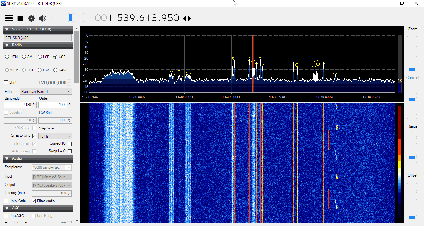
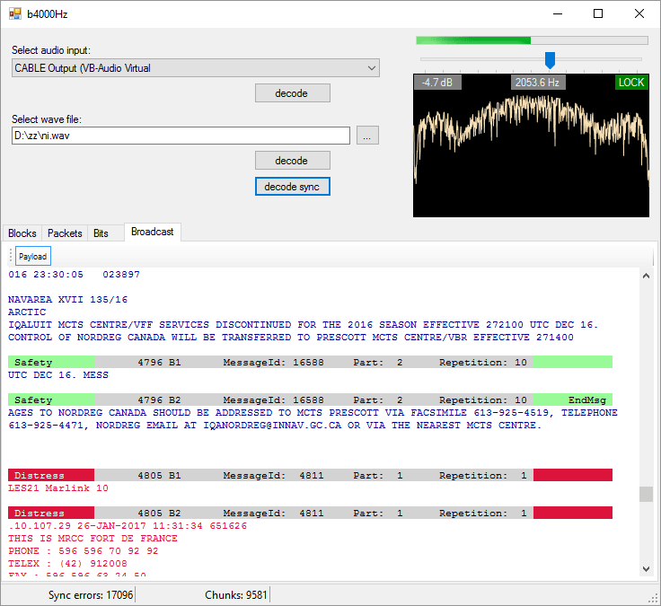
A new STD-C Inmarsat decoder called —-Hz has recently been released. The decoder is Windows based and simply listens to the demodulated Inmarsat STD-C audio from a program such as SDR#. This means that it is compatible with the RTL-SDR, and any other SDR that can receive Inmarsat.
We gave the software a brief test and it ran very well, and managed to decode several SafeteNET messages without issue, maintaining a good lock most of the time. The author writes that he plans to improve on the software in the future by creating a web service based version of the software.
Currently there are two other Inmarsat decoders available. One is called InmarsatDecoder and the other is the Tekmanoid decoder. The InmarsatDecoder is generally regarded as the best, but the Tekmanoid decoder was recently updated for improved performance. The new software appears to be about the same as the Tekmanoid decoder.
Inmarsat STD-C messages are broadcast from geostationary satellites in the L-band at around 1.5 Ghz. They send mostly marine based messages such as the following quoted from the ——Hz website:
Safety: high seas, tropical storm warnings, ice accretion…
Shipping activity: moving oil rigs, submarine cable deployment and repairs…
Distress reports: MOB, ships lost at sea, migrant ship reports…
Military exercises (firing practice, no fly zones…)
Pirate at sea reports…
If you are interested in learning how to decode STD-C we also have a tutorial available here.

![[EN subs] Outernet Case aus dem 3D Drucker (Universal elv. Winkel) - für DIY Kit](https://www.rtl-sdr.com/wp-content/plugins/wp-youtube-lyte/lyteCache.php?origThumbUrl=https%3A%2F%2Fi.ytimg.com%2Fvi%2F6KBdvhVP_fM%2F0.jpg)