Yesterday we posted about Lucas Teskes (@lucasteske) success in building a demodulator for the GOES weather satellite. Before that he also showed us how to build an antenna system to receive GOES with an Airspy or RTL-SDR dongle.
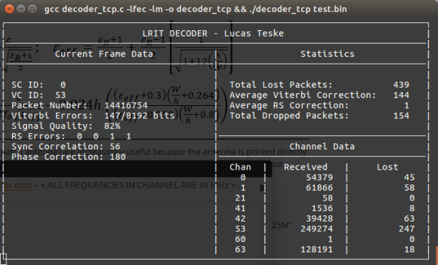
Today Lucas continues with part three of his series on GOES decoding. This time he shows how he has built a frame decoder to process the output of the demodulator, and also gives us a link to his code. The decoder is written in C code. Lucas’ post explains how to sync the frame by detecting the preamble, perform convolution encoding to generate a parity and help correct any errors, and decode the frame data.
In part four Lucas will show us how to parse the frame data and extract the packets which will eventually form an image file of the earth.
A decode frame viewed as an image. This shows the syncword pattern and frame counter.
Last week we posted about Lucas Teske’s (@lucasteske) experience with setting up an antenna system that can receive the geostationary GOES weather satellites. He set up a dish antenna, feed, LNA and filter and was able to successfully receive the GOES signal with an RTL-SDR and Airspy.
Now Lucas has uploaded his second post where he discusses how to demodulate the GOES signal. The GOES satellites transmit a Low-Rate Information Transmission (LRIT) signal which contains full disk images of the earth as well as other weather data from the secondary Emergency Managers Weather Information Network (EMWIN) signal.
In order to demodulate the signal Lucas wrote a BPSK demodulator in GNU Radio. His post goes into good technical detail and shows exactly how the demodulator is constructed. Basically the the BPSK signal is first decimated down to 2.5e6, normalized with an AGC, then cleaned up with a Root Raised Cosine Filter. From there the signal goes through a Costas Loop PLL to receover the carrier wave, then a Clock Recovery MM block to recover the symbol clock. The data is then output to a TCP pipe for the decoder.
In the upcoming third part of his article Lucas will show us how to actually turn the demodulated data into an image of the earth.
Many people with an RTL-SDR have had fun receiving NOAA and METEOR low earth orbit (LEO) weather satellite images. However, a step up in difficulty is to try and receive the geostationary orbit (GEO) weather satellites like GOES. These satellites are locked to a fixed position in the sky meaning there is no need to do tracking, however since they are much further away than LEO satellites, they require a 1m+ satellite dish or high gain directional antenna to have a chance at receiving the weak signal. The GOES satellites transmit very nice high resolution full disk images of the earth, as well as lots of other weather data. For more information see this previous post where we showed devnulling’s GOES reception results, and this post where we showed @usa_satcom’s presentation on GOES and other satellites.
The nice thing about Lucas’ post is that he documents his entire journey, including the failures. For example after discovering that he couldn’t find a 1.2m offset satellite dish which was recommended by the experts on #hearsat (starchat), he went with an alternative 1.5m prime focus dish. Then after several failed attempts at using a helix antenna feed, he discovered that his problem was related to poor illumination of the dish, which meant that in effect only a small portion of the dish was actually being utilized by the helix. He then tried a “cantenna”, with a linear feed inside and that worked much better. Lucas also discovered that he was seeing huge amounts of noise from the GSM band at 1800 MHz. Adding a filter solved this problem. For the LNA he uses an LNA4ALL.
To position the antenna Lucas used the Satellite AR app on his phone. This app overlays the position of the satellite on the phone camera making it easy to point the satellite dish correctly. He also notes that to improve performance you should experiment with the linear feeds rotation, and the distance from the dish. His post of full of tips like this which is very useful for those trying to receive GOES for the first time.
In future posts Lucas hopes to show the demodulation and decoding process.
GOES signals received with the dish, LNA4ALL, filter and an Airspy.
Over on YouTube well known SDR tester Leif (SM5BSZ) has uploaded a video that compares the performance of several HF receivers with two tone tests and real antennas. He compares a Perseus, Airspy + SpyVerter, BladeRF + B200, BladeRF with direct ADC input, Soft66RTL and finally a ham-it-up + RTLSDR. The Perseus is a $900 USD high end HF receiver, whilst the other receivers are more affordable multi purpose SDRs.
If you are interested in only the discussion and results then you can skip to the following points:
24:06 – Two tone test @ 20 kHz. These test for dynamic range. The ranking from best to worst is Perseus, Airspy + SpyVerter, Ham-it-up + RTLSDR, Soft66RTL, BladeRF ADC, BladeRF + B200. The Perseus is shown to be significantly better than all the other radios in terms of dynamic range. However Leif notes that dynamic range on HF is no longer as important as it once was in the past, as 1) the average noise floor is now about 10dB higher due to many modern electronic interferers, and 2) there has been a reduction in the number of very strong transmitters due to reduced interest in HF. Thus even though the Perseus is significantly better, the other receivers are still not useless as dynamic range requirements have reduced by about 20dB overall.
33:30 – Two tone test @ 200 kHz. Now the ranking is Perseus, Airspy + SpyVerter, Soft66RTL, BladeRF+B200, Ham-it-up + RTLSDR, BladeRF ADC.
38:30 – Two tone test @ 1 MHz. The ranking is Perseus, Airspy + SpyVerter, BladeRF + B200, ham-it-up + RTLSDR, Soft66RTL, bladeRF ADC.
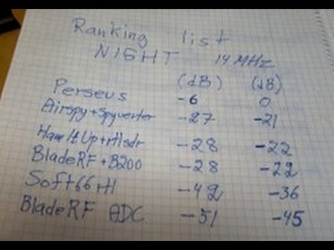
50:40 – Real antenna night time SNR test @ 14 MHz. Since the Perseus is know to be the best, here Leif uses it as the reference and compares it against the other receivers. The ranking from best to worst is Airspy + SpyVerter, ham-it-up + RTLSDR, BladeRF B200, Soft66RTL, BladeRF ADC. The top three units have similar performance. Leif notes that the upconverter in the Soft66RTL seems to saturate easily in the presence of strong signals.
1:13:30 – Real antenna SNR ranking for Day and Night tests @ 14 MHz. Again with the Perseus as the reference. Ranking is the same as in 3).
rx1compare
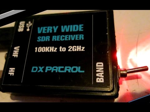
In a previous video Leif also uploaded a quick video showing why he has excluded the DX patrol receiver from his comparisons. He writes that the DX patrol suffers from high levels of USB noise.
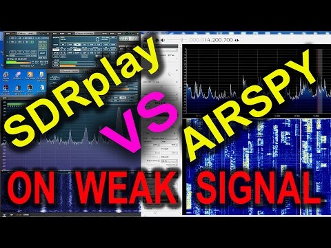
Over on YouTube two new videos comparing the reception on the SDRplay and Airspy have been uploaded. The first is by Mile Kokotov and he compares the reception on a very weak broadcast FM station, with several strong signals surrounding it. He writes:
In this video I am presenting Airspy+SDR# vs SDRplay+SDRuno in the real world, receiving very weak FM broadcast station in the terrible conditions, with very strong signals around. The Weak signal was in the lower edge of the FM broadcast spectrum, with very strong local signals close to the weak one, in the upper frequencies of the FM broadcast spectrum. The antenna for the both SDR receivers was the same – Vertical Dipole for FM BC band.
Both SDR receivers were tuned to maximum possible signal to noise ratio (SNR) of the weak FM broadcast signal.
In SDRuno RSP control panel (for SDRplay receiver) ZERO IF and 0.3/0.6 bandwidth were chosen, and the weak signal of interest was placed on the right edge of IF filter, so that the strong signals from other FM broadcast radio stations were placed right from the weak one in order to minimized the negative influence to the our weak signal. LNA was switched off. When the LNA was on, there where high distortion level because LNA was overloaded from the strong signals, and SNR was deteriorated regardless of gain reduction. The best results were achieved with gain reduction set to “0”, without LNA.
In SDR# software (for Airspy SDR receiver) 10 MSPS and Decimation was used. From the version 1480, in SDR#, when decimation is choosed, there is tracking filter which allow better selectivity, so you can use more gain, increasing the SNR to maximum possible level depending of concrete situation.
The overall receiving conditions was extremely bad. The signals from local FM radio stations were too strong so the weak signal from this video can not be received at all, with many expensive FM tuners which I tried: Pioneer VSX 527, Denon AVR-1802, Marantz SR6300. I was tried RTL-SDR just for fun, but it can not receive weak signal too :-), not because SDR-RTL is not sensitive enough, but because its dynamic range is not so high and it is overloaded by too strong local signals.
The very sensitive receiver is not problem to design and produce. Much more difficult is to design a high dynamic range receiver. which will be able to receive very weak and very strong signals at the same time without overloading.
Overloaded receiver front end means that it is not linear any more, and produces many signals by itself, increasing its noise level. Very strong signals at the receiver front end makes Desensitization of the receiver, so it could not receive weak signals any more. We should not forget that the receiver front end “looks” all signals from the wide frequency range even if we want to receive only one signal at the time. The more wideband the receiver is, the higher dynamic range it has to be, for not been overloaded…
SDRplay and Airspy receiving Very WEAK FM broadcast signal
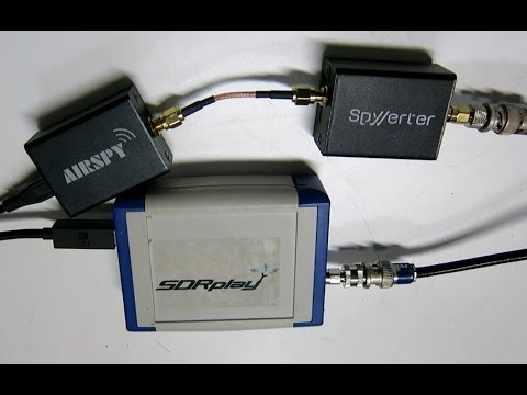
In the second video Leif sm5bsz compares the Airspy+SpyVerter with the SDRplay RSP on HF reception. He concludes that the difference between the two radios on HF is small. However, Youssef from Airspy has contested the result, noticing that Leif ran the Airspy at 2.5 MSPS, resulting is significantly less decimation being used. In response Leif updated his video adding an A/B comparison on HF with the Airspy correctly running at 10 MSPS in the last 8 minutes of the video. The results seem to show that the SDRPlay and Airspy+Spyverter have similar HF performance, but when comparing maximum decimation on the Airspy and the smallest bandwidth the SDRplay to obtain similar bandwidth’s, the results seem to show that the Airspy+SpyVerter is about 5 dB more sensitive at receiving weak signals.
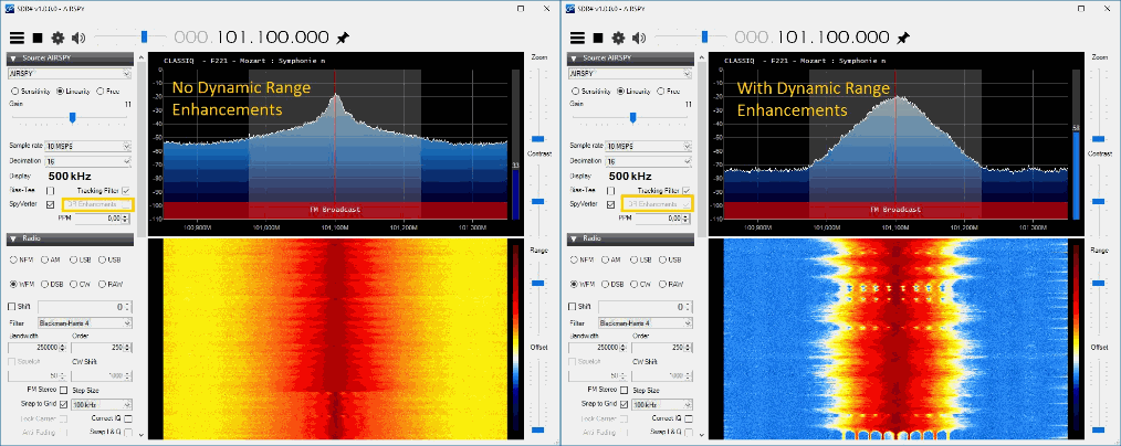
In a previous post we posted about how SDR# had been updated to vastly improve on the CPU usage. The author has been hard at work once again, and has now released a new update which significantly improves the dynamic range with the Airspy SDR. The new update gives a boost of up to 12dB in dynamic range when using decimation. This means that the gains can be turned up further without overloading occurring, and that weaker signals can come in much stronger without strong signals overloading and drowning them out.
The example images show some examples of the dynamic range improvements.
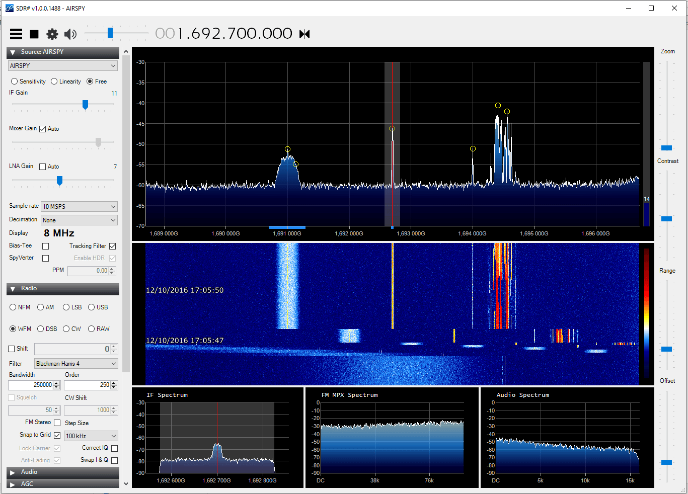
An example of the improved dynamic range for the Airspy on the latest SDR#.Using decimation removes overload.
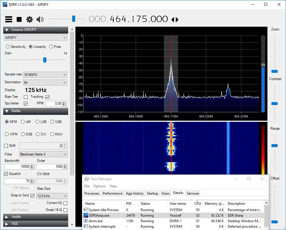
Recently the popular SDR# (SDRSharp) software has had several improvements made to it (changelog). One of the most noticeable improvements is a decent reduction in the amount of CPU usage required by the software. We tested the new version on an i7 CPU and compared it against an older version using an Airspy. We saw 12% CPU usage on the older version and 7% on the newer version. With the RTL-SDR the older version showed 5% CPU usage which reduced to 3% on the newer version. Using an older i5 PC resulted in even larger improvements, going from about 35% CPU on the older version down to 25% or lower usage on the new version with the Airspy. The improvements are especially noticeable when decimation is used with the Airspy. These performance updates may help users on older PC’s and tablets run the software, or help users who run many programs at one time. The SDR# author is also testing out a 64 bit version of SDR#, which may be released in the future.
Recent versions over the past few months have also made improvements to the included noise blanker plugins and they have also added a default band plan plugin which shows the various frequency bands visually on the FFT spectrum.
Showing the very low CPU usage obtainable with the latest SDR# versions.
The Geostationary Operational Environmental Satellite (GOES) is a weather satellite placed in geosynchronous orbit (same position in the sky all the time) which is used for weather forecasting, severe storm tracking and meteorology research. It transmits full disk images of the earth on its Low Rate Information Transmission (LRIT) signal, and weather data images and text on its Emergency Managers Weather Information Network (EMWIN) signal. EMWIN is a service for emergency managers that provides weather forecasts, warnings, graphics and other information in real time.
In his post devnulling writes about receiving GOES:
GOES LRIT runs at 1691.0 MHz , EMWIN is at 1692.7 MHz and is broadcasted from GOES-13 and GOES-15. GOES-14 is currently in a backup position to take over in either fails.
For the hardware side, it is recommended to use roughly a 1.2m or larger dish, depending upon how far north you are, you may need a 1.8m dish (larger the better). Repurposed FTA or C-band dishes are easy to come by and work well.
I made a 5 turn helical feed with some 12ga copper wire and a piece of copper plate, and used this calculator to design it – https://jcoppens.com/ant/helix/calc.en.php
I have a short run of coax into the LNA/Filter box. The first LNA is a TriQuint TQP3M9037 which has a very low noise figure (0.3 dB NF and 22 dB gain at 1.7 GHz).
That is ran into a Lorch 1675 MHz filter (150 MHz pass band), then a LNA4ALL and another Lorch before going over a 30ft run of RG-6 to the SDR.
I am using @usa_satcom (twitter.com/usa_satcom, usa-satcom.com)’s LRIT Decoder and that feeds into XRIT2PIC to produce the images and other data streams. By default the decoder only works with the Airspy, but with a custom GNU Radio UDP block, it can be fed with other SDRs like the BladeRF/USRP/SDR Play. A regular R820T(2) RTL probably won’t work because of the higher frequency (rtls tend to not work above 1.5 GHz) and 8 bit ADC. I’m going to try and use the Outernet e4k to see if I can pickup the EMWIN signal in the near future.
EMWIN is broadcasted on 1692.7 MHz, along with being encoded in the LRIT stream at 1691 MHz. The 1692.7 MHz signal is stronger and narrower, so it is easier to pickup. For decoding EMWIN I used @usa_satcom’s EMWIN decoder that piped data into WxEmwin/MessageClient/Weather Message Server from http://weathermessage.com.
LRIT will contain the full disk images from GOES-15, and relayed images from GOES-13 and Himawari-8. It will also included zoomed in pictures of the USA, and northern/southern hemispheres. The images will be visible light, water vapor and infrared. The full disk images are transmitted every 3 hours, with the other images more often. EMWIN will contain other weather data, text, charts, and reports.
It seems as though it may be possible to receive LRIT and EMWIN signals with an RTL-SDR since the signals are at 1690 MHz, which should be covered by cooled R820T2 and E4000 dongles. The only hardware requirements would be a 1m+ dish, 1690 MHz L-band feed, and an LNA + filter.
In 2017 these satellites are due to be replaced by new ones that will use a HRIT signal, which will be about 1 MHz. New software to decode this signal will be required then, but we assume the same hardware could still be used as the frequency is not due to change significantly.
Please note that the decoding software is only available by directly contacting usa-satcom, and devnulling writes that you must have the proper equipment and be able to show that you can receive the signal first before attempting to contact him.
GOES Full Disk ImageOne of several received EMWIN images