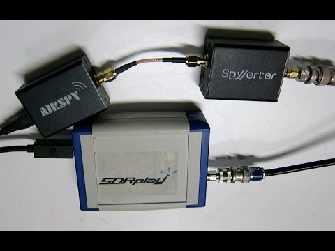
Over on YouTube well known SDR tester Leif (SM5BSZ) has uploaded a video that compares the performance of several HF receivers with two tone tests and real antennas. He compares a Perseus, Airspy + SpyVerter, BladeRF + B200, BladeRF with direct ADC input, Soft66RTL and finally a ham-it-up + RTLSDR. The Perseus is a $900 USD high end HF receiver, whilst the other receivers are more affordable multi purpose SDRs.
If you are interested in only the discussion and results then you can skip to the following points:
24:06 – Two tone test @ 20 kHz. These test for dynamic range. The ranking from best to worst is Perseus, Airspy + SpyVerter, Ham-it-up + RTLSDR, Soft66RTL, BladeRF ADC, BladeRF + B200. The Perseus is shown to be significantly better than all the other radios in terms of dynamic range. However Leif notes that dynamic range on HF is no longer as important as it once was in the past, as 1) the average noise floor is now about 10dB higher due to many modern electronic interferers, and 2) there has been a reduction in the number of very strong transmitters due to reduced interest in HF. Thus even though the Perseus is significantly better, the other receivers are still not useless as dynamic range requirements have reduced by about 20dB overall.
33:30 – Two tone test @ 200 kHz. Now the ranking is Perseus, Airspy + SpyVerter, Soft66RTL, BladeRF+B200, Ham-it-up + RTLSDR, BladeRF ADC.
38:30 – Two tone test @ 1 MHz. The ranking is Perseus, Airspy + SpyVerter, BladeRF + B200, ham-it-up + RTLSDR, Soft66RTL, bladeRF ADC.
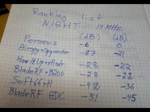
50:40 – Real antenna night time SNR test @ 14 MHz. Since the Perseus is know to be the best, here Leif uses it as the reference and compares it against the other receivers. The ranking from best to worst is Airspy + SpyVerter, ham-it-up + RTLSDR, BladeRF B200, Soft66RTL, BladeRF ADC. The top three units have similar performance. Leif notes that the upconverter in the Soft66RTL seems to saturate easily in the presence of strong signals.
1:13:30 – Real antenna SNR ranking for Day and Night tests @ 14 MHz. Again with the Perseus as the reference. Ranking is the same as in 3).
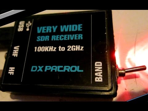
In a previous video Leif also uploaded a quick video showing why he has excluded the DX patrol receiver from his comparisons. He writes that the DX patrol suffers from high levels of USB noise.