Airspy HF+: An upcoming low cost yet high performance HF SDR
Over on the Airspy Yahoo forums and Twitter we’ve seen news of an upcoming new product from the developers of the Airspy SDR. The new product is called the Airspy HF+ and will be a low cost, yet extremely high performance HF specialty radio.
Preliminary specs:
- HF coverage between DC .. 31 MHz
- VHF coverage between 60 .. 260 MHz
- -138 dBm MDS
- -142 dBm MDS at 500Hz bandwidth in VHF
- +26 dBm IIP3 on HF at maximum gain
- +13 dBm IIP3 on VHF at maximum gain
- 110 dB dynamic range in HF
- 95 dB dynamic range in VHF
- 120 dB Image Rejection
- Very low phase noise PLL (-110 dBc/Hz @ 1kHz separation @ 100 MHz)
- +10 dBm Maximum RF input
- Wide Band RF filter bank
- Tracking RF filters
- Sharp IF filters
- Smart AGC with real time optimization of the gain distribution
- All RF inputs are matched to 50 ohms
- 2 x High Dynamic Range Sigma Delta ADCs @ 36 MSPS
- 600 kHz alias and image free output
- 18 bit DDC
- 0.5 ppm high precision, low phase noise clock
- 4 x Programmable GPIO’s
- No drivers required! 100% Plug-and-play on Windows Vista, Seven, 8, 8.1 and 10
- Industrial Operating Temperature: -45°C to 85°C
Basically, this addresses the lack of affordable and good performing receivers for HF and VHF.
Target price < $200
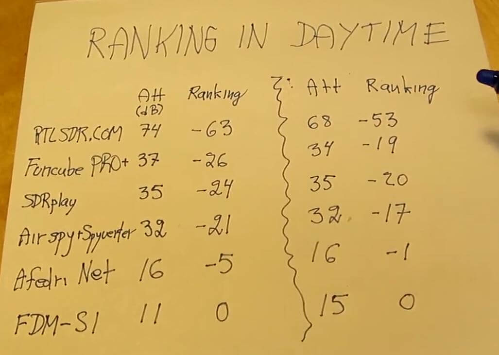
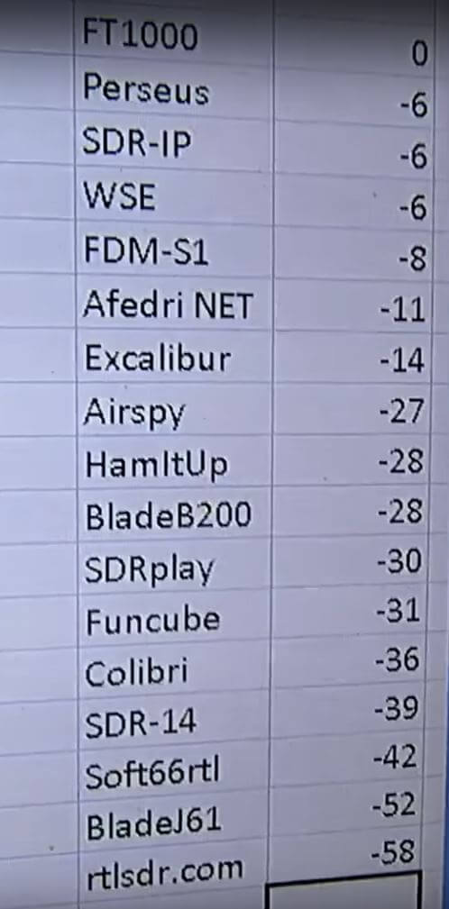
As with all Airspy products the SDR focuses on achieving extremely high dynamic range. From the specs is seems that the dynamic range and image rejection will be high enough so that even extremely strong broadcast AM or FM stations will not require any filtering or attenuation. They are also confident enough to say that no gain sliders will need to ever be adjusted to avoid overload.
For SWLers and MW DXers this seems like the ideal SDR as it should perform as well as high end SDRs like the Perseus, RFSpace and Elad SDRs, but at a fraction of the price.
[tweet id=”https://twitter.com/lambdaprog/status/833081845474533378″ align=”center”]
The product is still in development and no release date has been offered yet, but judging from the Twitter feed the prototype is already working.