John, DK9JC N1JJC wanted to set up an RTL-SDR APRS packet iGate. APRS stands for “Amateur Packet Reporting System”, and is a type of packet radio communications system used by Amateur Radio operators. They often use them to transmit short messages, weather sensor updates, and for vehicle tracking. An iGate allows APRS messages to be transmitted over the all world via the internet like so RF->iGate RX->Internet->iGate TX->RF.
When trying to receive the APRS packets John discovered a problem. He discovered that there was a very strong 100kW broadcast FM and 50kW DAB transmitter on a transmission tower in line of sight of his antenna. The strong signals were overloading the dongle and completely wiping out the APRS packets that he was trying to receive at 144.8 MHz.
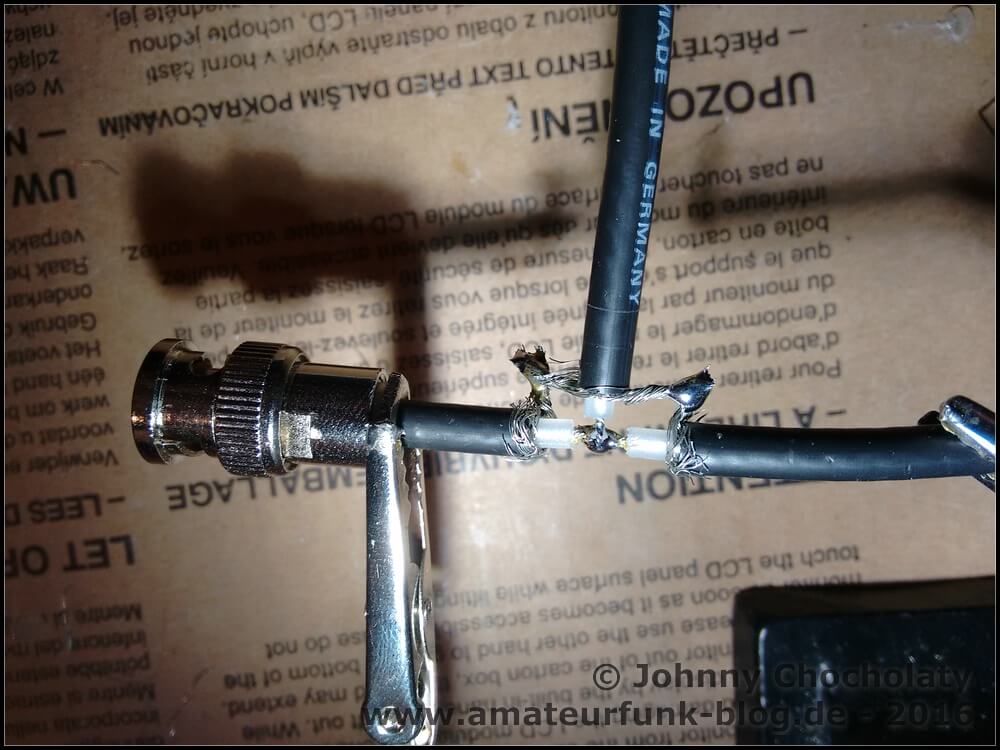
First John tried a simple bandpass filter with 0.8 dB insertion loss and 20dB attenuation. The filter still wasn’t enough, so he went and made a several coax notch filters to take out each of the interfering signals. A coax notch filter is simply a length of coax connected via a “T” junction to the main coax cable. This creates a notch of attenuation at a frequency depending on the length of the notching coax. With these notches combined with the bandpass filter he was finally able to receive APRS packets.
In this post we will review the FlightAware ADS-B Antenna and their 1090 MHz band pass filter. The FlightAware ADS-B antenna is claimed to have 5.5 dBi of gain, a rugged weatherproof radome and N-type female connector. It costs $44.95 USD on Amazon for US customers and $54.95 USD on eBay for international customers (plus shipping). They write that they are selling this antenna at cost in order to improve FlightAware coverage.
The FlightAware ADS-B filter is a bandpass filter with a pass range of 980MHz - 1150MHz, ~1.5dB insertion loss and more than 40dB attenuation of unwanted frequencies. It costs $19.95 USD on Amazon for US customers and $24.99 USD on eBay for international customers (plus shipping). Generally it is much cheaper than other ADS-B filter options on the market.
FlightAware.com is a company that specializes in aggregating ADS-B data from contributors around the world. People can contribute by using the FlightAware official hardware, or with a simple SDR, like an RTL-SDR dongle. They display the data on their website as it can be used to help track flight arrival times. A similar company is flightradar24.com.
If you are interested in getting started with ADS-B reception with your RTL-SDR then we have a tutorial here.
FlightAware ADS-B Antenna
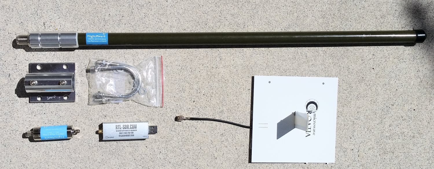
The FlightAware antenna is about 64cm in length and about 2cm in diameter. It uses an N female connector and comes included with mounting brackets and U-bolts. It is painted olive green.
In the photo below we compare the size of the antenna against a reference monopole antenna, an RTL-SDR dongle and the FlightAware ADS-B filter. The antenna appears to be very solidly built and of a high quality finish. The antenna is wareproofed with some silicon caulking used around the seams of the endcaps.
Size comparison
The FlightAware ADS-B antenna is a collinear type antenna. Collinear antennas are omnidirectional (receives equally from all directions) and have a higher gain compared to most other omnidirectional antennas, but their radiation pattern is flattened and directed more towards the horizon. This is a good thing for receiving planes that are far away as they will be at lower elevations, but aircraft at higher elevations relative to your antenna may be received poorer. Although, it is likely that any aircraft at high elevations to your position will be closer to you anyway, and thus have a stronger signal making the reduced gain at higher elevations less important. Judging by it's ~60cm length and it's specified gain of 5.5dBi, the FlightAware antenna is likely to be a 4 element collinear.
A 4 element collinear generally has positive gain from 0 - 20 degrees of elevation, whereas a simple dipole or ground plane may have positive gain from between 0 - 40 degrees of elevation. A typical commercial jet flys at about 10km. At a distance of 100km this jet would be at a 5.7 degree elevation, and at 10km 45 degrees. Smaller aircraft fly at about 3km maximum, and at 100km would have an elevation of 1.7 degrees, and at 10km 16.7 degrees, so the collinear covers most cases.
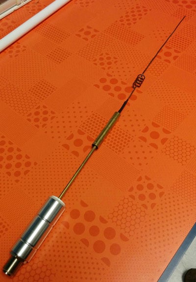
A reader wrote in to us to let us know that the internals of the FlightAware antenna had actually previously been posted in an old thread on their forums. From the image it looks like the antenna may be a sleeved dipole + whip + impedance matching design, or something similar. This design is somewhat of a collinear design thanks to the additional whip which also gives a flatter radiation pattern with more gain direction out towards the horizon. These antennas are omnidirectional (they receive equally from all directions) and have a higher gain compared to most other omnidirectional antennas, but their radiation pattern is flattened and directed more towards the horizon. This is a good thing for receiving planes that are far away as they will be at lower elevations, but aircraft at higher elevations relative to your antenna may be received poorer. Although, it is likely that any aircraft at high elevations to your position will be closer to you anyway, and thus have a stronger signal making the reduced gain at higher elevations less important.
The internals of the FlightAware antenna.
If you live in a valley, or have multiple obstacles such as trees or buildings blocking your view of the horizon then the higher gain design may work worse than a dipole/quarter wave ground plane/folded monopole type antenna. In this situation you'd mainly only be able to receive ADS-B signals from higher elevations, so an antenna with a less flat radiation pattern would work better. See the end of this post for some example radiation pattern diagrams.
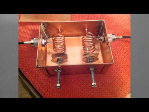
Over on YouTube user Mile Kokotov has uploaded a video showing his home made low loss helical bandpass filter for 145 MHz, but also tunable from 110 MHz to 160 MHz. Bandpass filters are useful for the RTL-SDR as often strong out of band signals can cause overload, causing poor reception. A bandpass filter blocks all signals outside of its pass band. A helical bandpass filter is simply a coiled wire enclosed in a conductive container that can be tuned with a variable capacitor made out of two plates.
In his video Mile shows the inner construction of his helical filter, explains the parts and shows what calculations he used for construction.
145 MHz Low Loss Bandpass Helical Filter by Mile Kokotov
Over on YouTube Adam Alicajic has posted a video showing how much a bandpass filter at the front end of an RTL-SDR can significantly improve reception. He points out that it is a myth that modern software receivers do not need preselector filters at the front end for best performance.
He tests the RTL-SDR with and without a front end 2m triple helical bandpass filter on a CW beacon at around 144 MHz. With the filter on there is almost a 10dB improvement in signal reception.
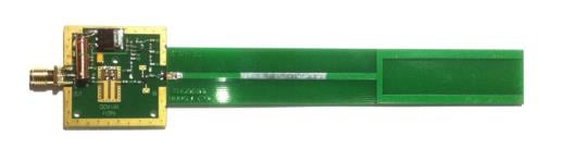
This ADS-B antenna by amateur radio hobbyist F5ANN combines a 30dB LNA preamplifier, bandpass filter and antenna tuned for 1090MHz together on a single PCB board. The LNA preamplifier helps boost weak signals, whilst the bandpass filter helps to remove interference from others signals such as GSM. The novel thing about this antenna is that everything is neatly packaged into a single PCB board, which makes this antenna very compact, and yet have high performance.
F5ANN uses his combined antenna together with an RTL-SDR dongle and the RTL 1090 ADS-B decoding software with PlanePlotter, and was able to receive 194 simultaneous aircraft signals with a message rate of 556 messages a second at distances of up to 250 nm.
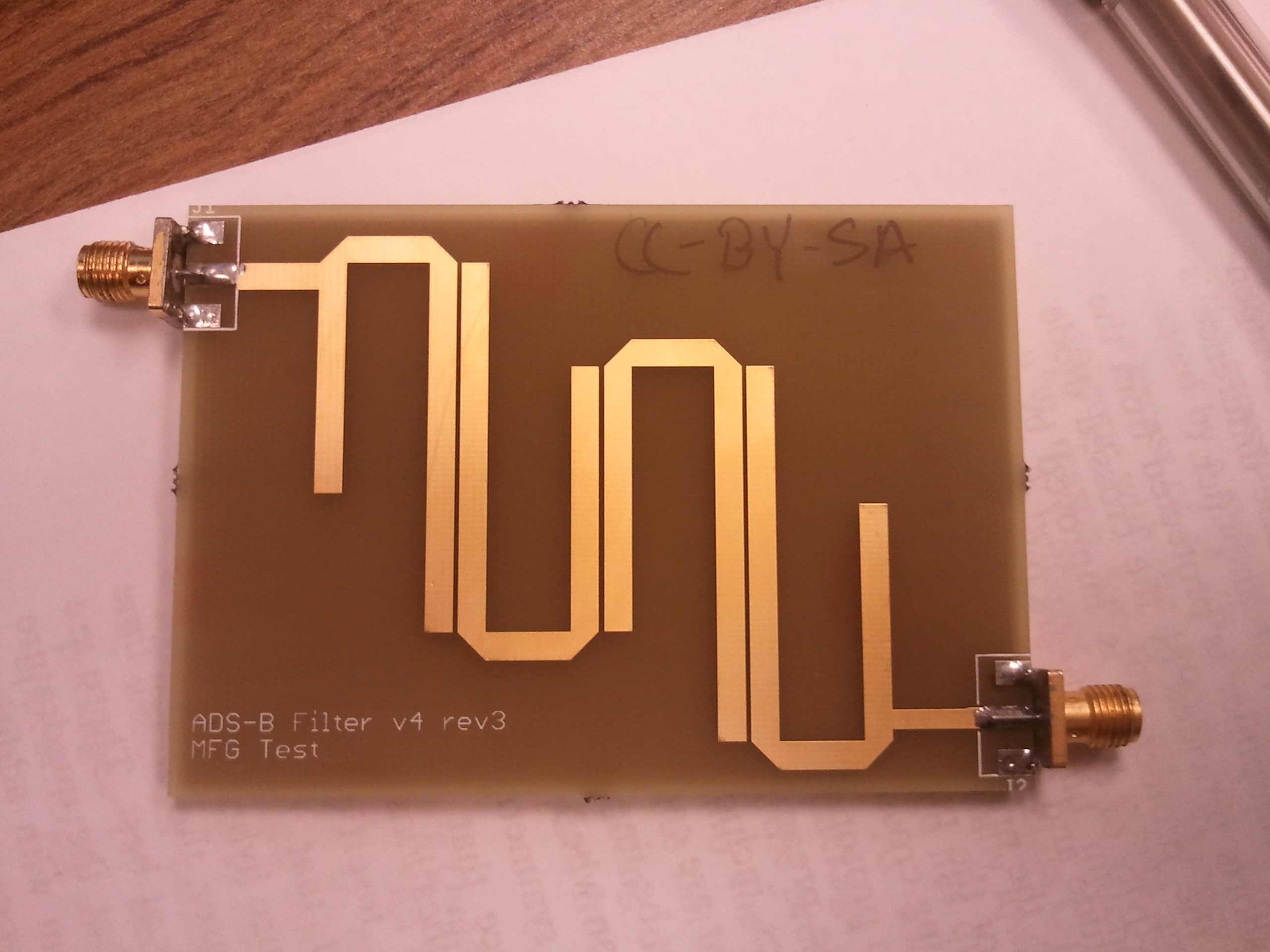
Reddit user BigReid has posted on the Reddit rtl-sdr forums his homemade bandpass filter with a pass range of 1-1.2GHz for improving adsb reception. A bandpass filter blocks any interference from signal frequencies outside of the pass range. This might be useful for adsb if you experience a lot of interference from out of band signals at 1090MHz.
His filter is a hairpin filter, which can easily be etched onto a PCB board. You can find the PCB schematic files linked on the post.