Testing the Electrosense Up/Downconverter Expansion Board For 0 – 6 GHz
The Electrosense network is an open source project aiming to deploy radio spectrum sensors worldwide. The idea is to help analyze and understand radio spectrum usage across the globe. Each sensor consists of an RTL-SDR, Raspberry Pi and an optional downconverter to receive the higher bands. If you're interested we wrote an overview of the project in a previous post.
Recently we received a sample of their Up/Downconverter expansion board which is used to expand the frequency range of the RTL-SDR to 0 MHz to 6 GHz. The converter board is entirely open source with the design files available on GitHub. The team note that they are also working on a V2 version which will be cheaper and smaller. The schematic and Firmware for the V2 is also available right now, but it is still under early testing and may change.
The board is not for sale, however you can apply to be considered for a free unit if you want to host your own Electrosense node and meet their criteria. If you do not you can still produce the board yourself. The team mention that the design is easily hand soldered, but there are a few difficult LGA components like the PLL, crystals and mixer which require a heat gun to solder. A the same time they also note that it is possible to get PCB manufacture and SMT assembly done for you for dirt cheap by PCB prototype companies like JLC PCB.
The Expansion Up/Downconverter Board
The converter board has 4-input SMA ports (only 3 are used) and one output port which connects to the RTL-SDR. The first input port is for the HF antenna input. This input connects to the circuit which converts 0 - 30 MHz into a higher frequency which can be received by the RTL-SDR. The second port is simply a pass through for the standard 24 MHz - 1.766 GHz range of a normal SDR. The third port is unused, and the fourth port connects the antenna to the downconverter circuit which allows us to receive from 1.766 GHz to 6 GHz.
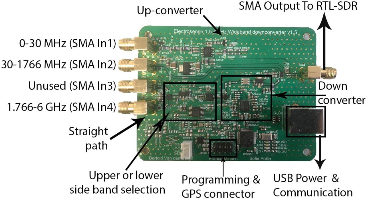
Frequency Control
There is also a USB port which is used to power and control the mixer on the converter. In this mixer controlled design the RTL-SDR stays tuned to the output IF frequency, which in the case of the downconverter is 1.576 GHz.
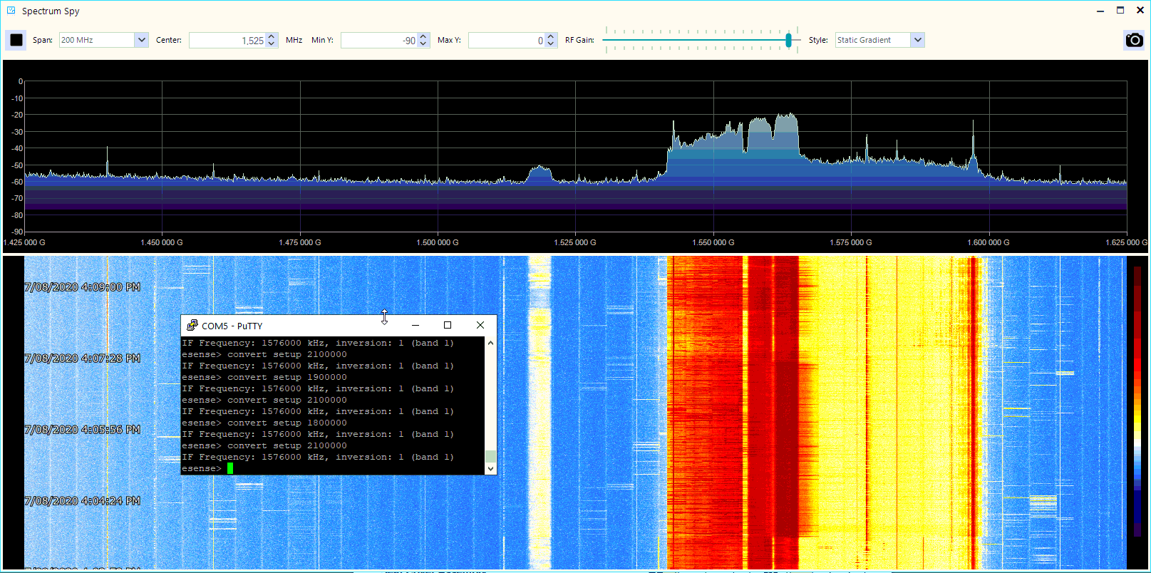
Tuning to different frequencies then is a matter of using the converters serial UART connection which can be connected to via USB and any terminal emulator software such as PuTTy for Windows. After plugging the unit into a Windows PC it will automatically install the drivers, and then you can check device manager for the COM port number.
Then for example, to receive the 2.4 GHz band, you would simply type the terminal command "convert setup 2400000" which would result in the 2.4 GHz spectrum being output at an IF frequency of 1.576 GHz. Note that the bandwidth of the IF output is limited to 50 MHz due to the SAW filter, and also we need to remember that the downconverted spectrum is inverted.
If you're interested in more information the extension board manual is available here, and information about the design here.
Testing
With Electrosense the converter board is used with RTL-SDR dongles as their own software sweeps through the bands logging signal levels. However in our tests we decided to use an Airspy Mini to create a wideband sweep via the Spectrum Spy software so that we had some clear spectrum images.
First we set the converter to receive the 2.4 GHz WiFi spectrum as shown below. We can clearly see the WiFi channels in use here.

In the next test we tuned to the much quieter 5.8 GHz WiFi spectrum. In the top recent section of the waterfall you can see where we began an internet speed test over our Google WiFi node which increased spectrum activity.

We also tested the 1.8 GHz and 2.1 GHz cellphone bands as shown below. Note that at the edges of the signals we can see the rolloff effect of the 50 MHz SAW filter.

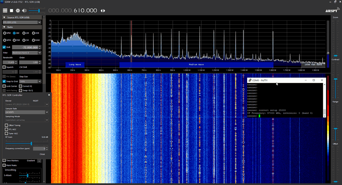
Finally we also tested the upconverter circuit with an RTL-SDR. This allowed us to easily receive broadcast AM with a chosen conversion upconvert frequency of 72 MHz.
Conclusion
The electrosense converter board is a very useful tool that can be used to expand the frequency range of any SDR like an RTL-SDR, Airspy or SDRplay device. The controllable mixer + SAW filtered IF design results in a clean signal, and almost zero signal imaging like what would occur on a wideband downconverter. However with the controllable mixer it requires an extra tuning step via the terminal.
Based on the BOM, building the device would cost roughly $80 in parts (cheaper in bulk) with the most expensive parts being the LTC5549 mixer and the MAX2870 PLL. Partial assembly for a few PCBs might cost $50. However the team note that once finished the V2 board will reportedly be about ~$25 cheaper in components.
With the introduction of $70 HackRF's being available on Aliexpress which can naturally tune from 0 MHz to 6 GHz with 20 MHz bandwidth, a converter board may not make that much sense for basic experimentation purposes in terms of price and as signals in the 2 GHz+ frequency bands are typically quite wideband. However, the converter board when combined with an RTL-SDR or higher end SDRs should offer better overall RX performance.
If you wish to try and obtain a free unit for hosting an Electrosense node, you can try and apply for an Electrosense sensor.


I don’t think so. Cause the LTC5549 has an x2 option on the pll input. That is, it can make the mixer works at 12G easily. But the input LNA is restricted at 6GHz max. I think that’s the main barrier.
Ah I forgot about that feature… that’s a very good point. I can’t tell from from the picture on the article if there’s any traces going to the 2x activator but it probably wouldn’t be too difficult to add it to the board design if there isn’t already that feature. In terms of the LNA, maybe the board can be re- designed to replace the ADL5602 with a MAAL-011130-TR3000 ? That IC covers from 2-18GHz
Whoops I meant to say SBB3089Z instead of ADL5602
May HMC8410 be more suitable?
It would definitely be an improvement over the SBB3089Z, but it would still only allow up to 10GHz which is good but not the full 12GHz of range. Plus it’s also pretty expenzive. Something like the AVA-183P+ or one of the options from Macom would probably be better, and Mouser and Digikey has a ton of other options for RF amplifiers
Hi,
It uses SBB3089Z as the frontend LNA, and the SBB3089Z is 50-6000MHz rf-amp. How to range it upto 13GHz?
There is the official tested operating range where validated parameters are shown in the datasheet, and then there operating outside that range.
Like in a LNA there is not a filter, because that would attenuate the signal and add additional noise. So you could drive it outside of the specification, but you do not know that is there once you have left the datasheet.
With the official range, you know that the gain (S21) is tested and validated to be pretty much flat over the entire official operating range. But operating outside of specification you could end up with attenuation instead of gain, or non linear gain or the signal could be attenuated below the noise floor.
Another example of operating outside of specification would be the the tuner chip (R820T2) in a typical RTL-SDR it has an official frequency range of 42 MHz to 1002 MHz (where the noise figure of 3.5 dB at maximum gain is valid).
Using a LNA rated up to 6GHz at 13.576 GHz (ref: https://github.com/electrosense/hardware/blob/master/electrosense-converter-firmware/firmware/drivers/system.c#L245 ) might work, or may not. But the source code has the option to tune it up to 13.576 GHz, to see if it works.
I want to know if it’s better to remove the frontend LNA for X-band extending? @Timmy @DutchHAM
Or if SBB3089Z can extend that faraway as accepted SNR?
Unfortunately I don’t think it would work up to 13GHz. The LTC5549 mixer in the downconverter does work up to 14GHz, but the PLL VCO acting as the LO only goes up to 6GHz. This means you can really only recieve up to about 7.5GHz, since the mixer is basically subtracting 6GHz (LO freq) from 7.5GHz (rx freq) which gives an output range of 1.5GHz. Although it would work higher than this, since any input higher than the LO frequency is subtracted from the LO freq, the problem is that an rtl-sdr can only recieve from ~27-1670MHz. If you had something like a Hackrf instead of an rtl-sdr, giving you a 6GHz maximum recieve freq, than you could recieve up to ~12GHz with this setup.
If you’re trying to recieve 13GHz with a normal rtl-sdr, I think a better option would be to make a downconverter with something like an LTC5549 as a mixer, and a VCO as the LO input, outputting at 6GHz with the LO multiplier of the LTC5549 on, which makes the LO freq 12GHz and should downconvert 13GHz down to the recievable range of the rtlsdr
You read the datasheet for the LTC5549 and saw “An internal LO frequency doubler can be enabled”, but the bit you missed is that the MAX2870 is not actually being used as a mixer, but as the LO for the LTC5549. So the LTC5549 can be tune from DC to 12GHz. Add to that the full bandwidth of the GPS filter being used and that boosts the range up to by 1.576 GHz to 13.576 GHz. It will probably be deaf as a post without some major external amplification, or a very large parabolic dish, but on paper it can tune up that high.
would that range be extended beyond 6Ghz if i had a bladerf on the output side ?
It receives up to 13GHz in the default config. Sensitivity is lower and there are no image reject filters but especially with an external filter and LNA it will receive well. Output is always in L-band so receiving device doesn’t matter.
I have one of the boards. It can receive the X band as well