ESP32 Bus Pirate: Update Brings Waterfall Displays, Cellular Modem Support and External Radio Expander
Back in September 2025, we posted about the "ESP32 Bus Pirate" firmware, which transforms an ESP32-S3 into a multi-protocol debugging and hacking tool. Although the ESP32 does not have true SDR capabilities, it can leverage its numerous built-in radio hardware components to achieve a range of interesting feats. Recently, "Geo," the creator of the ESP32 Bus Pirate, wrote in to share some recent firmware updates with us. He writes:
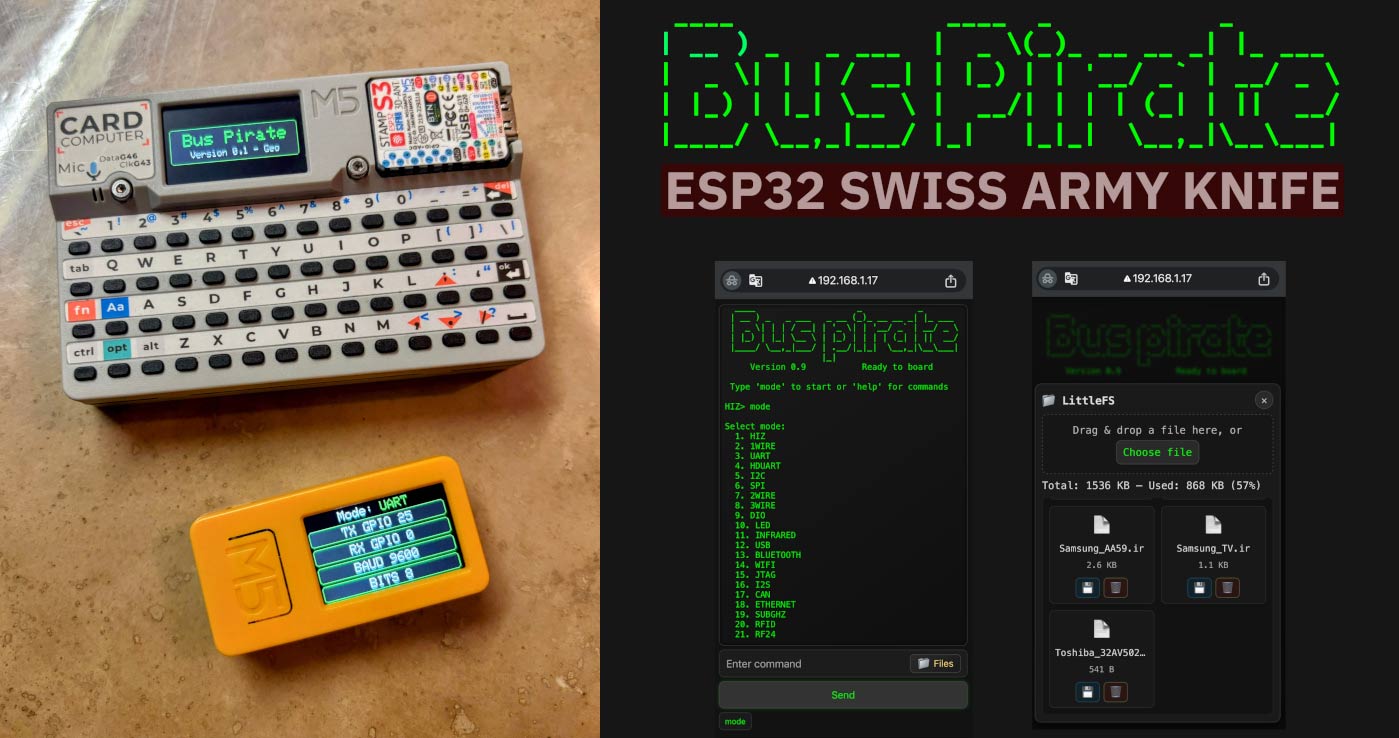
The ESP32-Bus-Pirate project is an open-source firmware that transforms inexpensive ESP32-S3 boards into versatile hardware hacking and debugging tools. Inspired by tools like the Bus Pirate and Flipper Zero, the firmware allows a single ESP32 device to interact with a wide range of digital buses, radios, and hardware interfaces.
Because ESP32 boards include integrated WiFi and Bluetooth radios and can interface with many external modules, the firmware makes it possible to experiment with both hardware protocols and RF systems using very low-cost hardware.
The firmware currently supports a wide range of protocols and devices including:
I²C, SPI, UART, CAN, 1-Wire, infrared, smartcards, Sub-GHz radios, RF24 modules, WiFi, Bluetooth and cellular modems.
Major New Features in v1.5
The latest release adds several major capabilities useful for hardware analysis and RF experimentation.
Waterfall Spectrum Displays
Multiple RF modules can now display real-time waterfall visualizations, showing signal peaks and activity across frequencies. This is available for:
• Sub-GHz radios
• RF24 modules
• FM radio modules
• WiFi channel activity
This makes it easier to visually monitor RF environments directly from the device.
Sub-GHz Improvements
The Sub-GHz subsystem has been completely reworked for improved reliability when recording, replaying and receiving RF frames. Raw payload transmission is also supported.
Cellular Modem Support
ESP32-Bus-Pirate can now interact with cellular modem modules, allowing users to inspect modem and network information and perform operations such as:
• Dumping SIM card data
• sending SMS
• dialing calls
External Radio Expander
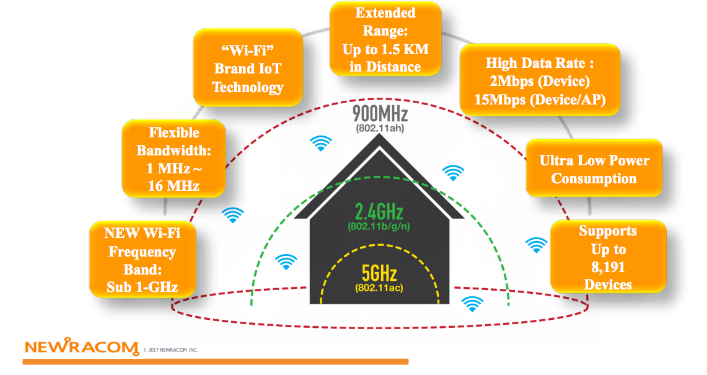
The firmware now supports an **external UART radio expansion module** called the **ESP32 Bus Expander**, which allows adding additional RF hardware modules to the system, notably for the WiFi 5GHz.
Links
Project:
https://github.com/geo-tp/ESP32-Bus-Pirate
Web Flasher:
https://geo-tp.github.io/ESP32-Bus-Pirate/webflasher/
Documentation:
https://github.com/geo-tp/ESP32-Bus-Pirate/wiki
Scripts collection:
https://github.com/geo-tp/ESP32-Bus-Pirate-Scripts
ESP32 Bus Expander:
https://github.com/geo-tp/ESP32-Bus-Expander