KiwiSDR: 30 MHz Bandwidth VLF to HF SDR now on KickStarter
Back on February 8 we posted about the up and coming KiwiSDR, a software defined radio with 30 MHz of bandwidth and a tuning range that covers 0 – 30 MHz (VLF to HF). It is intended to be a low cost web based SDR that can be accessed from all over the world via a browser interface.
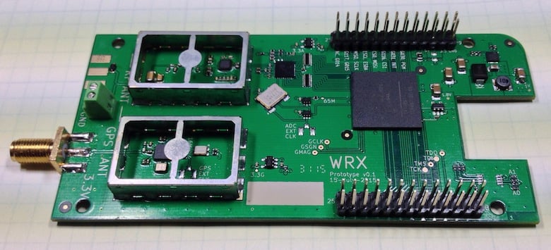
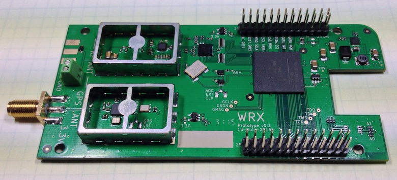
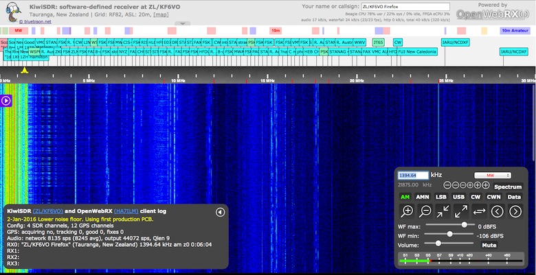
The KiwiSDR is designed as a cape for the BeagleBone Black mini embedded computer, and uses a LTC 14-bit 65 MHz ADC and Xilinx Artix-7 A35 FPGA. It also has an integrated SDR based GPS receiver which is used to automatically compensate for any frequency drift from the main 66.6 MHz oscillator. It runs on the OpenwebRX web based software, which many RTL-SDR users have already been using to stream live radio to the web.
Today the KiwiSDR started its crowd funding campaign on Kickstarter. A full KiwiSDR can be purchased for $199 USD, or for $299 including an enclosure, BeagleBone computer and GPS antenna. The fundraising goal is for $50,000 USD and if successful they estimate delivery in October 2016. The creators of the KiwiSDR write:
Sure, the world doesn’t really need another SDR. But we haven’t found one with this set of features. In cost and performance, KiwiSDR fits between RTL-SDR USB dongle-style, or fixed DDC chip devices ($20 – $400, 8-12 bit ADC, limited bandwidth), and full 16-bit SDRs ($700 – $3500) while offering better wide-band, web-enabled capabilities than the more expensive SDRs.
Our main motivation is to enable new applications which utilize a significant number of programmable, web-accessible SDRs world-wide. Direction finding remains one of the great under-solved problems of shortwave listening, particularly for utility stations. Given the GPS timing available on the KiwiSDR, could time-of-arrival techniques between cooperating SDRs be used? We’d sure like to find out.
Also, we’d like to see data decoders built directly into the web interface of KiwiSDR. There are many standalone programs that demodulate and decode data signals from SDRs. But these are computer- and OS-specific and often require a complicated interface to the data stream from the SDR. For example, we have a prototype of a WSPR decoder that is integrated into the KiwiSDR interface.
There are currently three KiwiSDR servers running publicly at the moment, and they can be accessed at:
http://kiwisdr.sk3w.se:8073
http://kiwisdr.ece.uvic.ca:8073
http://kiwisdr.com:8073