Mitigating QRM (Interference) with an Antenna Phaser
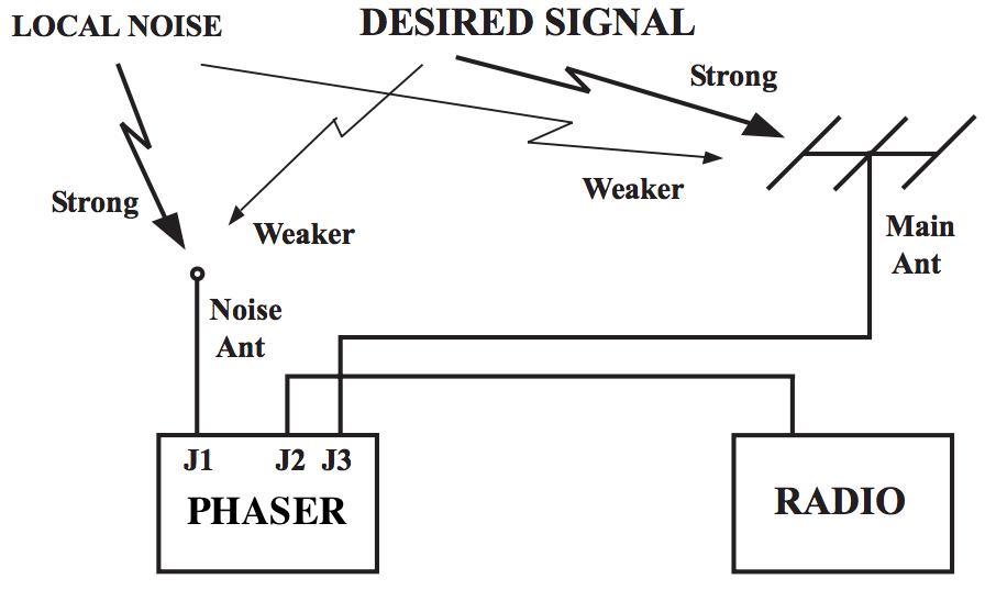
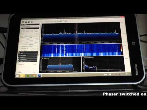
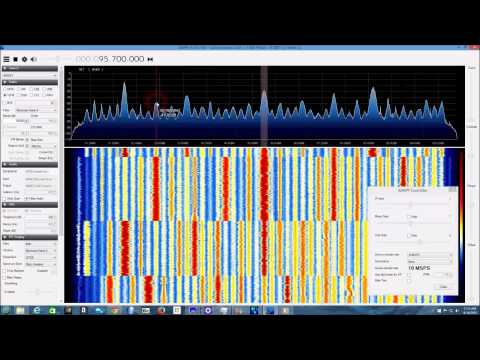
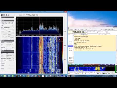
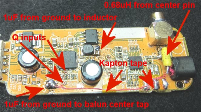
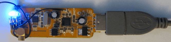
Over on YouTube user London Shortwave has posted a video showing his antenna phasing system in action with a Funcube Dongle Pro+ and SDR# running on a tablet. An antenna phaser reduces unwanted noise by using two antennas and positioning one “noise” antenna so that it receives the unwanted noise strongly, and positioning the main antenna to receive the desired signal as best as possible. Then the signals are combined by a phaser unit in such as way that the unwanted noise is subtracted from the desired signal.
In his experiments London Shortwave discovered that an ethernet over Power adapter used by one of his neighbours was causing the shortwave spectrum to get completely obliterated by noise. His video shows the effect of turning his phaser unit on and off when trying to reduce this noise. London Shortwave has also done a very nice writeup on dealing with urban interference on shortwave, and includes a section that discusses antenna phasing.