Measuring Frequency Deviation of an FM Transmitter with an RTL-SDR
Over on YouTube user KP4MD has uploaded a video showing how she uses an RTL-SDR together with SDR#, a program called Visual Analyzer and an AEA PK-232 Terminal Node Controller to measure the frequency deviation of a Yaesu FT-8800R Transceiver. She writes:
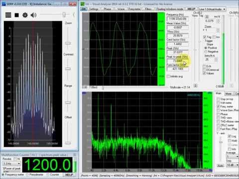
The SDR# receiver is tuned to 145.050 MHz and the bandwidth set to 20 kHz.
The deviation level of the 1200 Hz tone is increased until a null appeared on the carrier frequency.
This is called a Bessel Zero and occurs at various predicted modulation indices (2.4, 5.52, 8.66, etc).
The Modulation Index is defined as the peak frequency deviation divided by the modulation frequency.
This Bessel Zero occurred at a modulation index of 2.4 corresponding to a frequency deviation of ±2.88 kHz (2.4 x 1.2 kHz).
The oscilloscope indicates that a peak to peak amplitude of 54.3% corresponds to ±2.88 kHz deviation.
The 1200 Hz tone modulation is increased to yield a peak to peak amplitude of 66%.
This corresponds to the desired ±3.5 kHz frequency deviation.


I was just heading over here to share this find too.
Very interesting stuff.
What’s not mentioned is how the radio is coupled if at all. I’m assuming a dummy load would still radiate enough for a near by receiver.
Also not mentioned is the calibration or reference measurements. (Note: the 0 PPM correction in show in the video for SDR#.) She might be using a TCXO dongle.
Some of the plugins that are available for SDR# can do some of the work of the Visual Analyzer software. But there is room for a lot of improvement.
The tx radio is ‘coupled’ via indirectly via RF (dummy load/antenna).
Calibration of the RX PPM is another topic. Either way, the un-modulated carrier is obviously the center peak of the TX side-bands. Inject a sine wave (KHz) = deviation(KHz)/2.4. Adjust the deviation until the center carrier is at minimum in SDR. Visual Analyzer does not help when adjusting the deviation – unless you wish to confirm the RX sine wave frequency. Forget Visual Analyzer & peak-to-peak %. Just use the correct sine wave Khz for your desired deviation (2.5Khz deviation = 1.0416Khz sine wave. 5Khz deviation = 2.0833Khz sine wave. ) until the carrier is ‘null’.